
Spool winder

a winder and spool technology, applied in the direction of thin material processing, machines/engines, filament handling, etc., can solve the problems of snapping back to its original shape of a much larger diameter, difficult rewinding by hand without proper equipment, and quickly worn out monofilament lines, etc., to achieve easy wounding, minimal risk of slippage of the replaceable spool, and easy insertion

Inactive Publication Date: 2003-11-25
TRAVIS WELDON L
View PDF12 Cites 11 Cited by
  • Summary
  • Abstract
  • Description
  • Claims
  • Application Information

AI Technical Summary

Benefits of technology

It is an object of an embodiment of the present invention to provide a device that will support and hold a bulk roll of monofilament line and allow the line to be drawn off to a rewinding section to the device.
It is a further object of an embodiment of the present invention to provide a device that will support and hold a variety of replaceable line spools of differing sizes and shapes onto which a fresh supply of line can be easily wound from a bulk roll of the line.
It is an additional object of an embodiment of the present invention to provide a device that allows an empty replaceable spool to be easily inserted onto the device and held by a cranking device that rotates the spool winding the line onto the spool.
It is a further object of an embodiment of the present invention to provide a device that allows continuous tension to be applied to the line being drawn from the bulk spool with minimal risk of slippage of the replaceable spool.
It is an additional object of an embodiment of the present invention to provide a device that allows easy holding of the line that has been rewound on the replaceable spool to avoid the line springing off the spool and back to its original shape.
It is a further object of an embodiment of the present invention to provide an apparatus that can be held securely to a horizontal surface with one hand and wind the line from the supply onto the spool with the other hand.

Problems solved by technology

When the obstruction is abrasive, such a stones or concrete, the monofilament line is quickly worn away.
Rewinding by hand without proper equipment is difficult due the elastic memory of the line, which causes it to snap back to its original shape of a much larger diameter than the small replacement spools.
None of these devices satisfy the needs described above or attain the objects enumerated below.

Method used


Image

  • Spool winder
  • Spool winder
  • Spool winder

Examples


Embodiment Construction

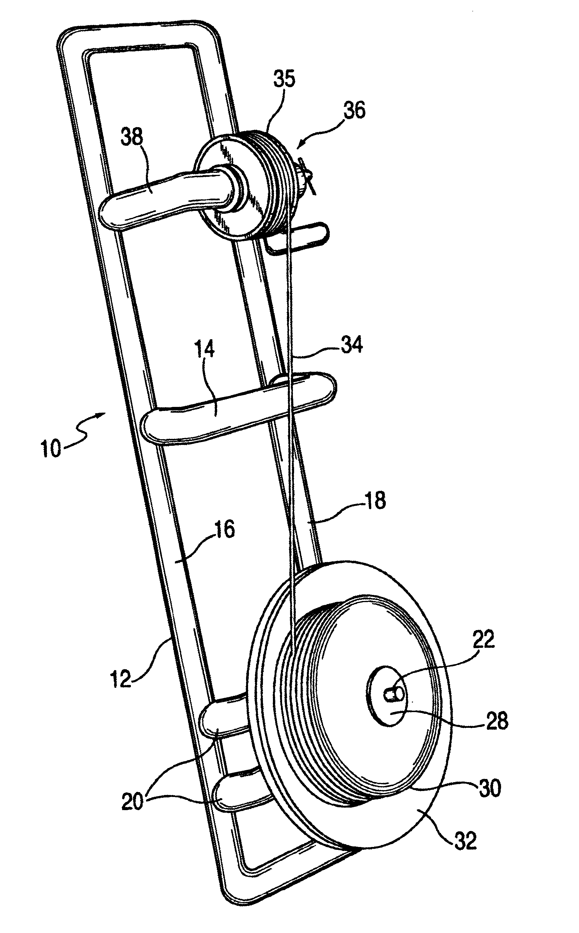
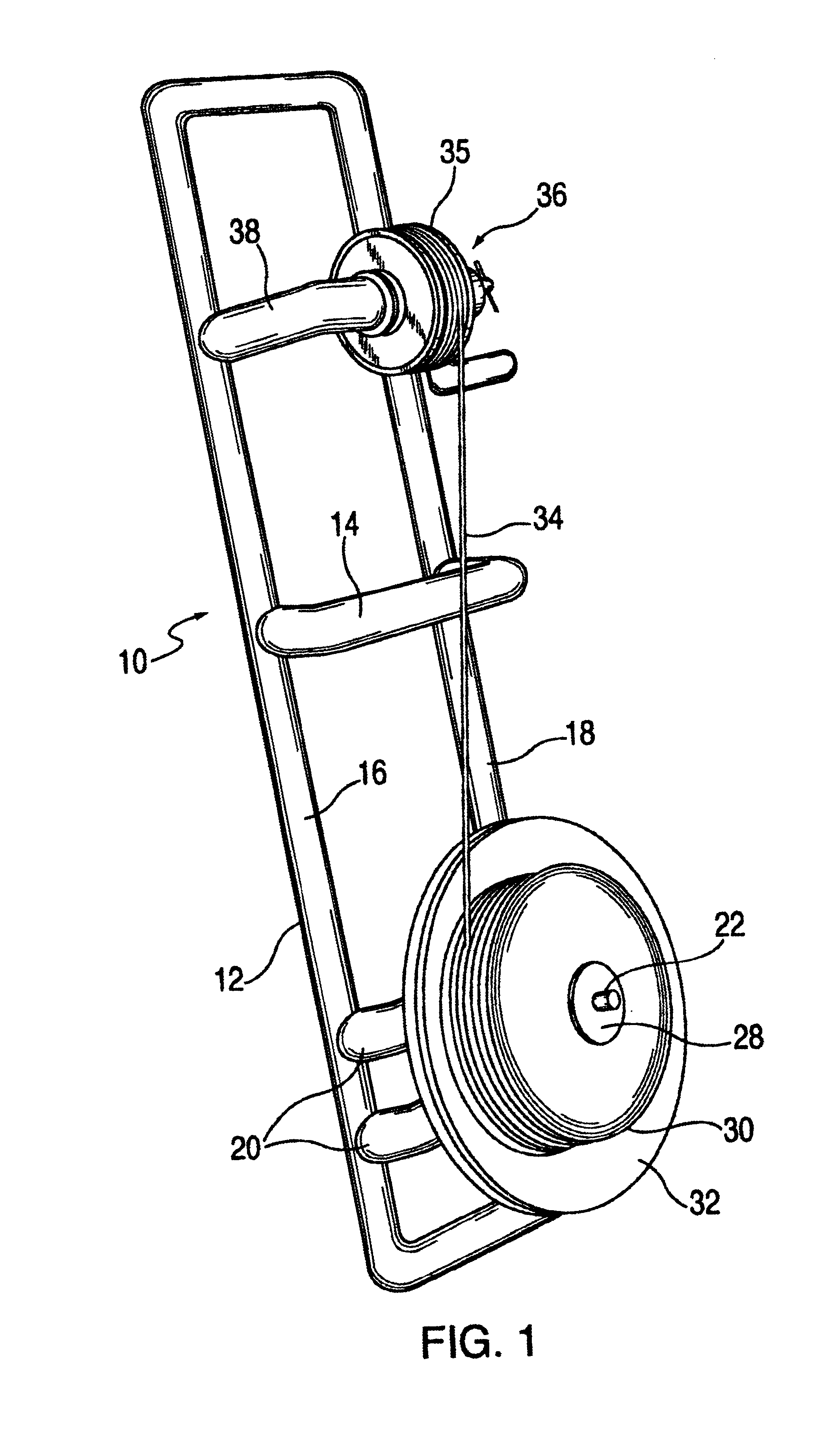
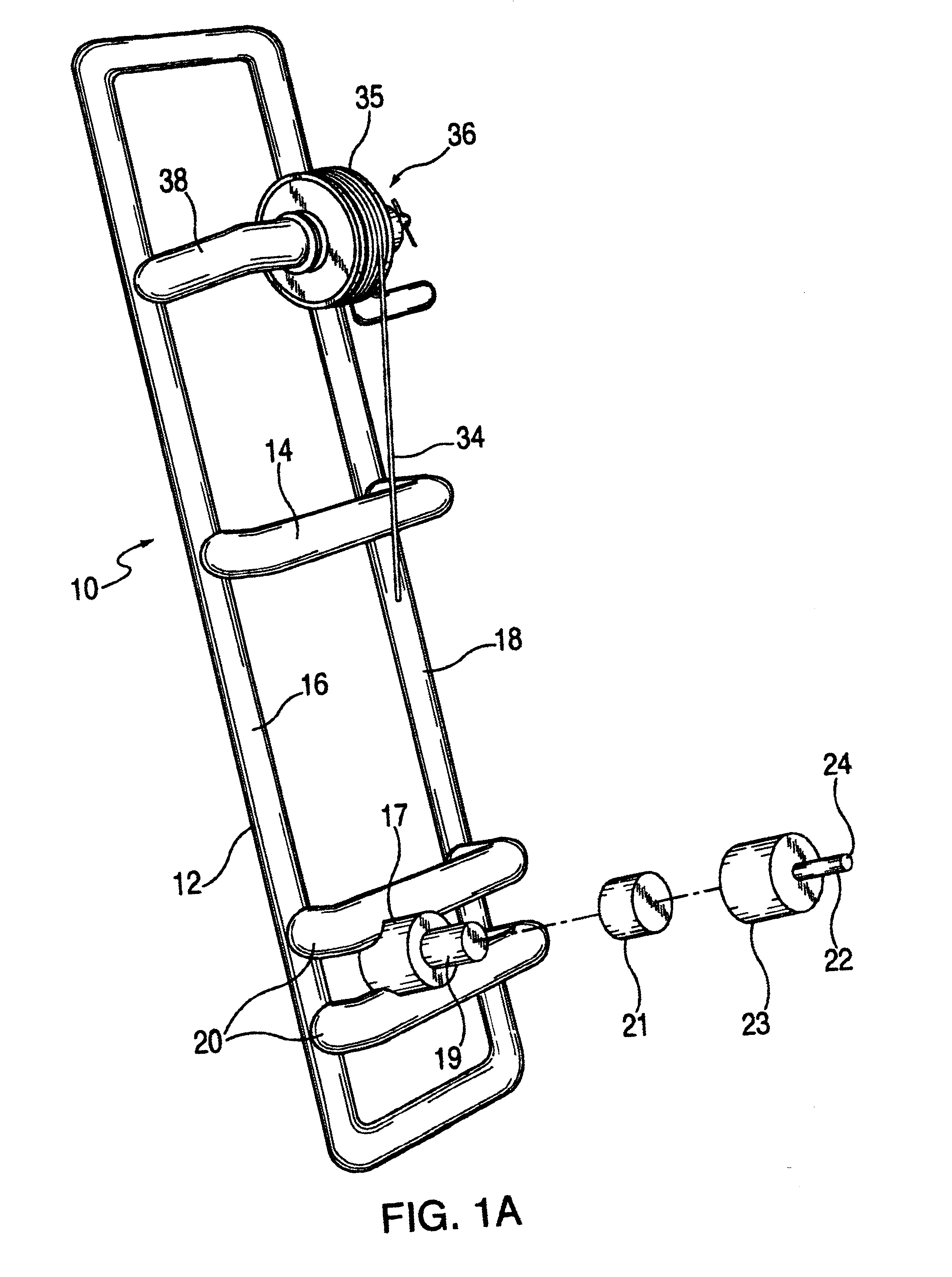
Spool winder apparatus 10, illustrated in FIGS. 1, 1A and 2, may be constructed entirely of polymeric plastic, such a rigid polyvinyl chloride, polystyrene, ABS, or preferably an engineering plastic, although certain parts such as cotter pins are more easily provided in metal. Apparatus 10 includes elongate rectangular base frame 12 with longitudinal side members 16 and 18 with upwardly extending inverted "U" shaped cross member 14 rigidly attached at its ends between the side members acting as a stiffener, a lifting handle and most importantly as a hand hold to securely hold the apparatus in place on a horizontal surface during the spool winding process. Frame 10 is also stiffened by cross members 20 extending between the side members proximate an end of the frame. Vertically disposed cylindrical base member 17 is rigidly attached centrally between cross members 20 with vertical rod member 19 attached to and extending upwardly from a top surface of base member 17. Inverted cup shap...


PUM


Abstract

A spool winder includes a holder for a filament bulk roll, a cantilever member to receive a weed trimmer filament spool, and a crank handle device rotating on the member while holding and interlocking into openings in the trimmer spool.

Description

This invention is directed to a device that allows the rewinding of monofilament line onto emptied spools of a variety commercially available lawn trimming devices.The monofilament line is quickly worn away during heavy use of the standard commercially available lawn trimmers, all of the design of the original WEED EATER.RTM. devices. All of these devices use a replaceable spool to hold and feed out the monofilament line to a length which when spun a high rate of speed cuts grass and weeds around essentially any obstruction. When the obstruction is abrasive, such a stones or concrete, the monofilament line is quickly worn away. For lawns with such obstructions a lot of line is used. The manufacturers of these trimming devices enjoy a good business of selling replacement spools with a fresh supply of monofilament line. Commercial lawn care companies and frugal homeowners with their own trimmers have purchased the replacement line in bulk packages and attempted to rewind the spools th...

Claims


Application Information

Patent Timeline
Patent Type & Authority Patents(United States)
IPC IPC(8): B65H49/00B65H54/00B65H75/30B65H49/28B65H49/32B65H75/18B65H54/10
CPCB65H49/28B65H49/32B65H75/30B65H54/106Y10S242/902B65H2701/354
Inventor TRAVIS, WELDON L.
Owner TRAVIS WELDON L
Learn More