Valve timing control system for internal combustion engine

a timing control system and internal combustion engine technology, applied in the direction of electric control, machines/engines, output power, etc., can solve problems such as affecting drivability

Inactive Publication Date: 2003-12-02
HONDA MOTOR CO LTD
View PDF7 Cites 22 Cited by
  • Summary
  • Abstract
  • Description
  • Claims
  • Application Information

AI Technical Summary

Benefits of technology

cleaning control means for forcibly driving the cam phase-varying device within a predetermined cam phase range when a predetermined delay time has elapsed after the deceleration fuel cut-off operation is started, to thereby prevent undesired locking of the cam phase-varying device.
According to the valve timing control system for an internal combustion engine, the cam phase-varying device causes the camshaft to rotate relative to the crankshaft to change the cam phase of an intake cam and / or an exhaust cam, whereby the valve timing for opening and closing an intake valve and / or an exhaust valve is controlled. Further, cleaning in which the cam phase-varying device is forcibly driven within a predetermined cam phase range is carried out when a predetermined time period has elapsed after the deceleration fuel cut-off operation was started. Thus, the cleaning is not carried out before the predetermined time period has elapsed after the start of the deceleration fuel cut-off operation. This causes the intake pipe pressure, which has been changed in a negative pressure-increasing direction due to full closing of the throttle valve immediately before the start of the deceleration fuel cut-off operation, to be increased toward the positive pressure side to some extent and made stable by the time the cleaning is started. Therefore, even if there occurs a large valve overlap between the intake valve and the exhaust valve due to subsequent execution of the cleaning, causing the positive pressure to be introduced into the intake pipe, the amount of change in the intake pipe pressure is small. Thus, a change of the intake pipe pressure in the negative pressure-increasing direction caused by the full closing of the throttle valve and a change of the same toward the positive pressure side caused by execution of the cleaning are produced in a distributed fashion with an appropriate shift in timing. This makes it possible to reduce the magnitude of an aftershock subsequent to the deceleration shock and makes it difficult to be felt by the driver as a shock, thereby improving drivability.
In general, the deceleration fuel cut-off operation terminates in a shorter time period as the gear ratio of the transmission is smaller since the engine brake is more effectively applied with a smaller gear ratio. Therefore, according to this preferred embodiment, since the delay time as a waiting time period before execution of the cleaning is set as described above, it is possible to appropriately secure the chance of execution of the cleaning, and increase the frequency of the same.
According to this preferred embodiment, even when the transmission is set to the smallest gear ratio in which the deceleration fuel cut-off operation terminates in a shortest time period, it is possible to appropriately secure the chance of execution of the cleaning.

Problems solved by technology

This pressure reaction increases the magnitude of an aftershock subsequent to a deceleration shock, causing the driver to feel a large shock, which impairs drivability.

Method used


Image

  • Valve timing control system for internal combustion engine
  • Valve timing control system for internal combustion engine
  • Valve timing control system for internal combustion engine

Examples


Embodiment Construction

The invention will now be described in detail with reference to the drawings showing a preferred embodiment thereof.

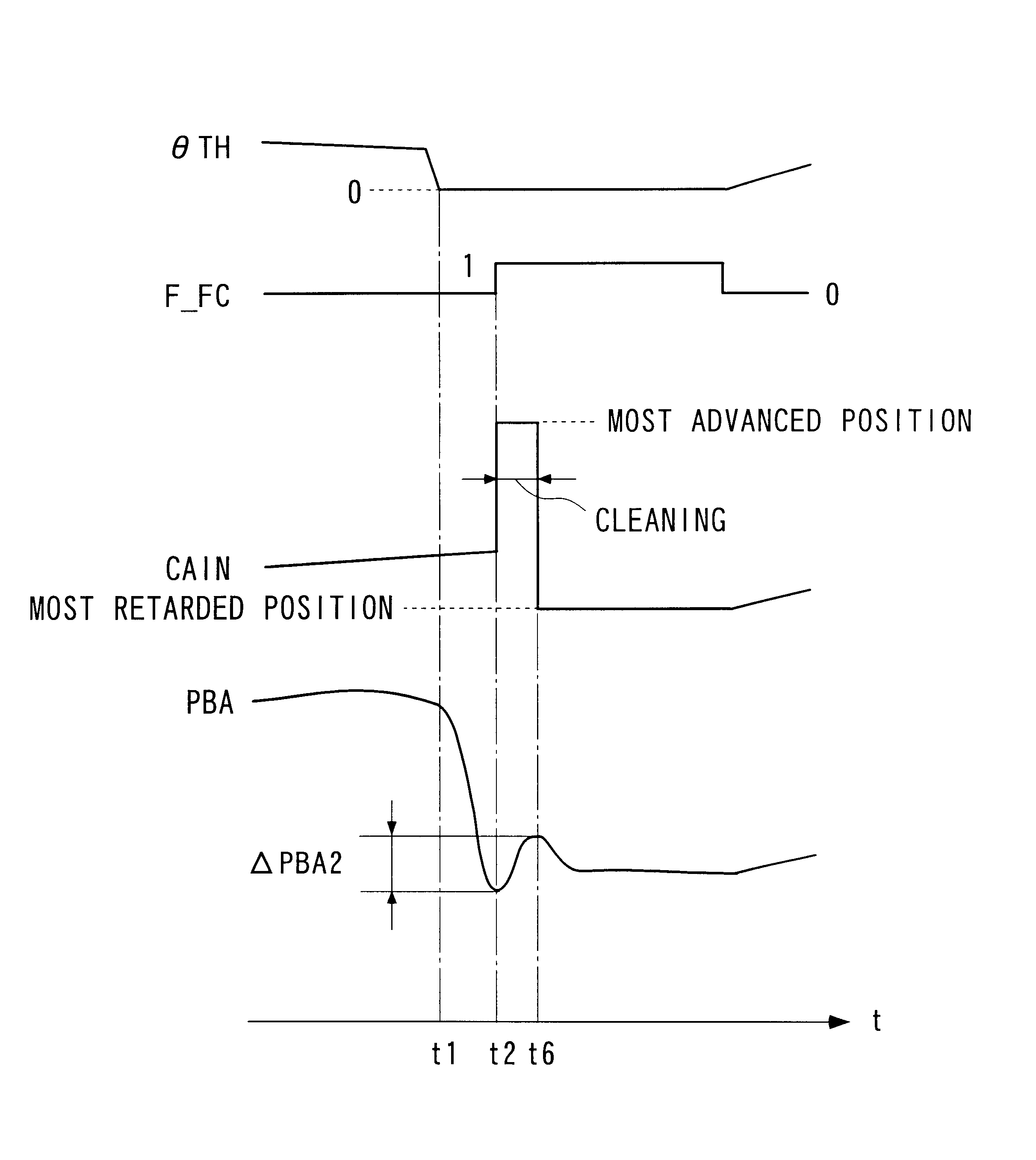
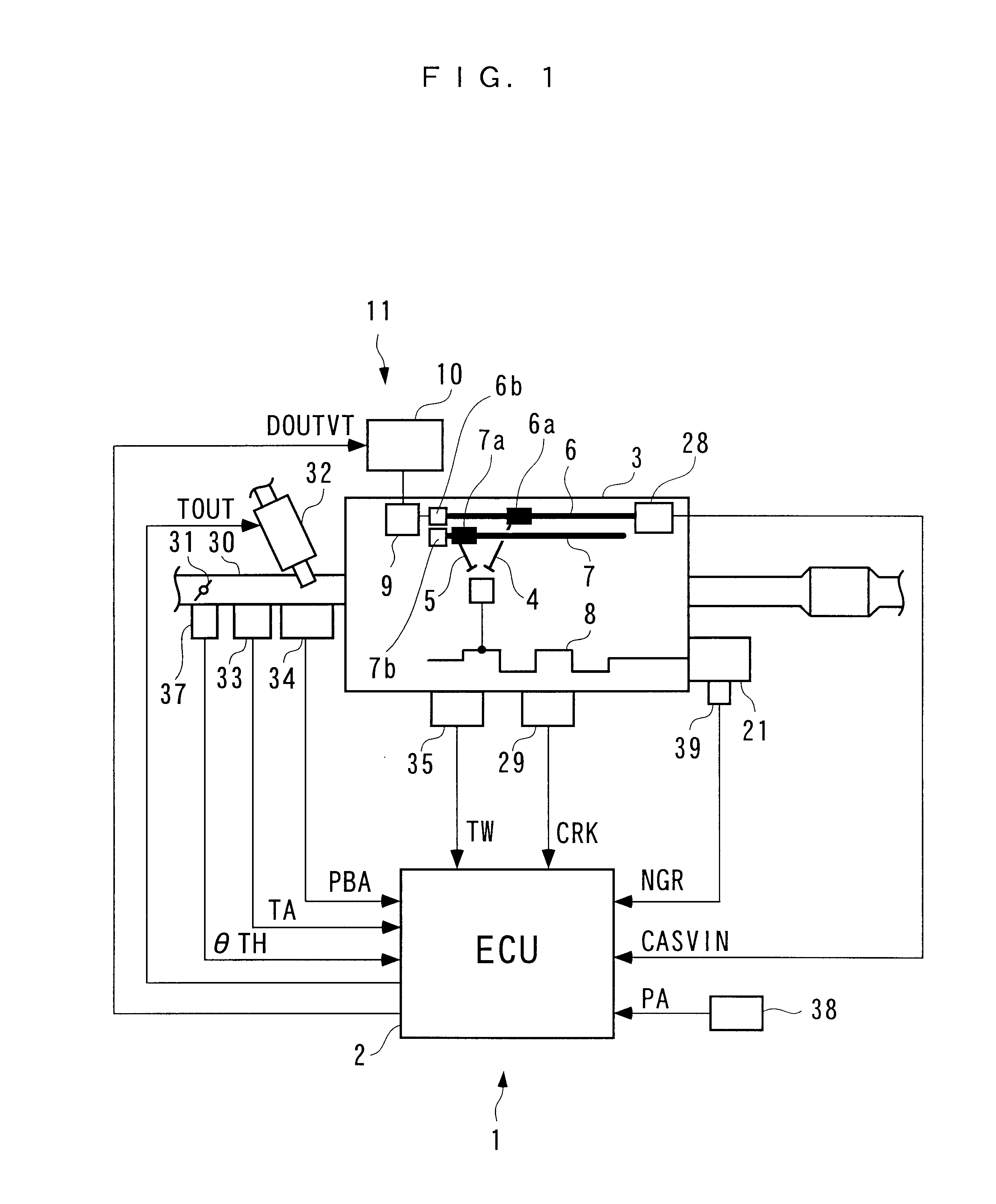
Referring first to FIG. 1, there is schematically shown the arrangement of an internal combustion engine incorporating a valve timing control system (hereinafter simply referred to as "the control system") according to an embodiment of the invention. As shown in the figure, the control system 1 includes an ECU 2. In the present embodiment, the ECU 2 forms or implements deceleration fuel cut-off operation-determining means, cleaning control means, and delay time-setting means, and carries out control processes, described hereinbelow, in dependence on operating conditions of the internal combustion engine (hereinafter simply referred to as "the engine") 3.

The engine 3 is e.g. a four-stroke cycle DOHC (double overhead camshaft) gasoline engine, installed on a vehicle, not shown. The engine 3 has a crankshaft 8 thereof connected to drive wheels (not shown) of the vehicle e...


PUM


Abstract

There is provided a valve timing control system for an internal combustion engine which is capable of reducing an aftershock subsequent to a deceleration shock, for which the execution of cleaning operation is responsible, and increasing the frequency of execution of the cleaning operation. The valve timing control system controls valve timing for opening and closing intake valves and / or exhaust valves by changing the cam phase of each intake cam and / or each exhaust cam relative to a crankshaft. A cam phase-varying device varies the cam phase by rotating a camshaft relative to the crankshaft. An ECU determines whether or not the engine is performing a fuel cut-off operation in which supply of fuel to the engine is stopped during deceleration. The ECU performs cleaning by forcibly driving the cam phase-varying device within a predetermined cam phase range when a predetermined delay time has elapsed after the deceleration fuel cut-off operation is started.

Description

1. Field of the InventionThis invention relates to a valve timing control system for an internal combustion engine, which varies the cam phase of at least one of an intake cam and an exhaust cam, relative to a crankshaft of the engine, to thereby control valve timing, and more particularly to a valve timing control system that executes cleaning to prevent undesired locking of a cam phase-varying device for varying the cam phase.2. Description of the Prior ArtA valve timing control system of this kind controls valve timing for opening and closing an intake valve and / or an exhaust valve and a valve overlap between the intake and the exhaust valve, by varying the cam phase, thereby controlling the charging efficiency and internal EGR of the engine, with a view to improving the power output thereof and reducing exhaust emissions therefrom. The valve timing control system is disclosed e.g. in Japanese Laid-Open Patent Publication (Kokai) No. 2000-104571. In this control system, a cam pha...

Claims


Application Information

Patent Timeline
Patent Type & Authority Patents(United States)
IPC IPC(8): F02D41/22F02D41/12F01L1/34F02D13/02
CPCF01L1/022F01L1/34F02D13/0219F02D41/123F02D41/22F02D13/0261F01L2001/34436F01L2800/00Y10T477/68F02D2041/001Y02T10/18Y02T10/12
Inventor FURUKAWA, TOMOYA
Owner HONDA MOTOR CO LTD
Why Eureka
Try Eureka