
Contact assembly for land grid array interposer or electrical connector

a contact assembly and land grid array technology, applied in the direction of coupling device connection, semiconductor/solid-state device details, instruments, etc., can solve the problems of not being able to meet the requirements of the application of the spring, not having a good spring material, etc., to achieve the effect of enhancing mechanical and electrical performance, enhancing electrical conductivity, and improving current carrying capacity

Inactive Publication Date: 2003-12-09
HIGH CONNECTION DENSITY INC
View PDF33 Cites 37 Cited by
  • Summary
  • Abstract
  • Description
  • Claims
  • Application Information

AI Technical Summary

Benefits of technology

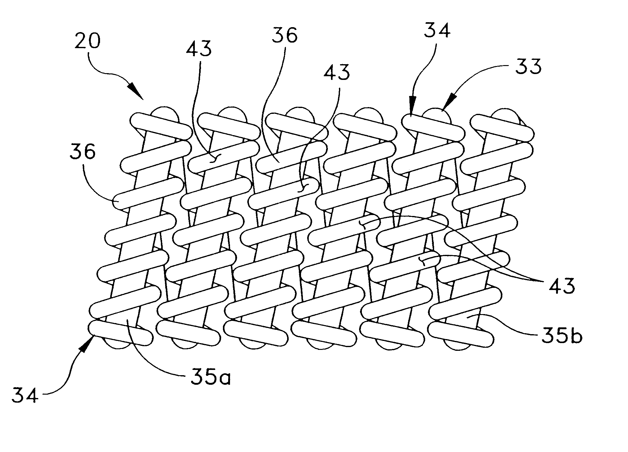
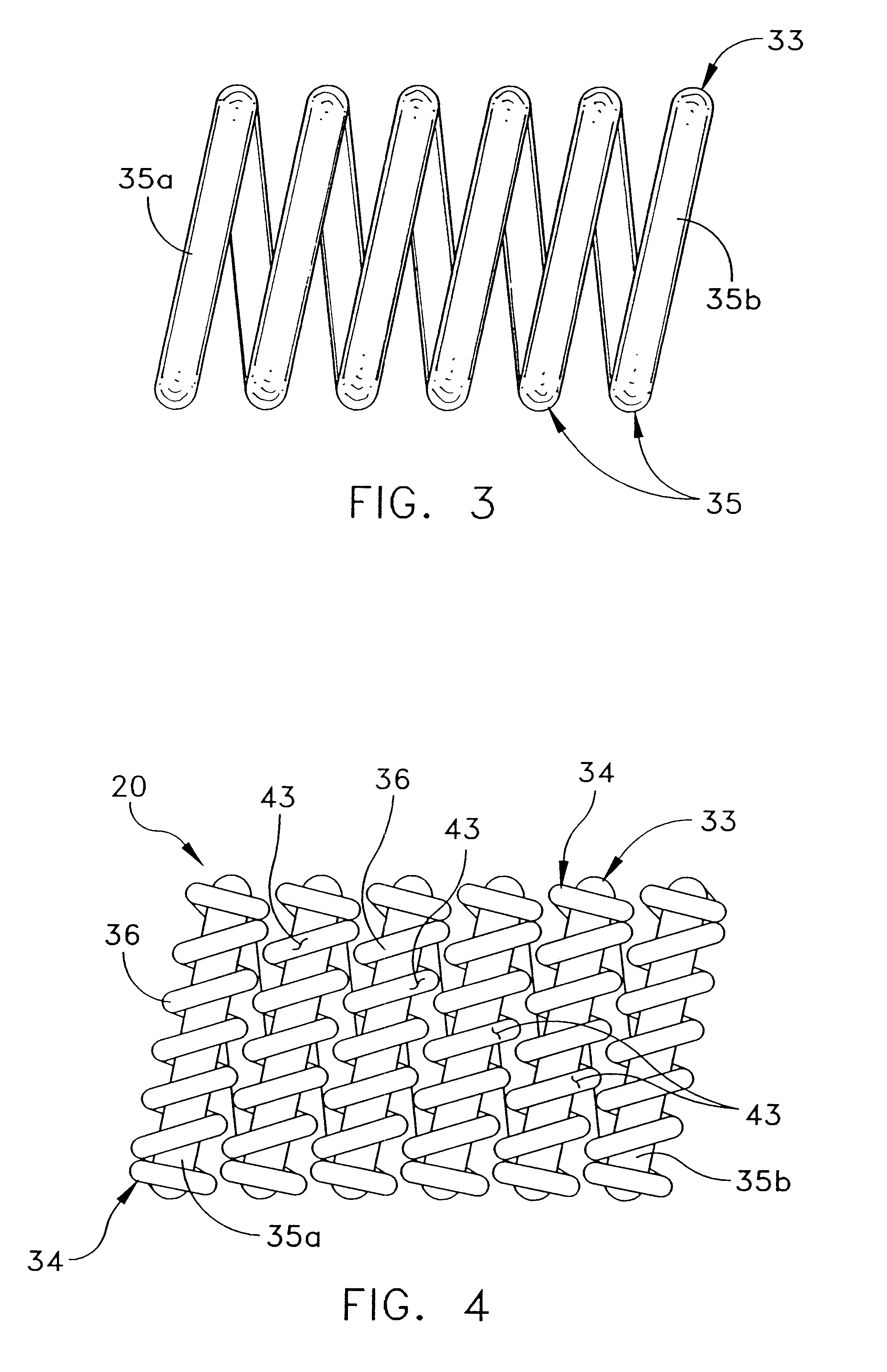
The present invention provides an electrical contact comprising a first member having spring properties and a second member wrapped around at least a portion of the first member wherein the second member has a greater electrical conductivity than the first member. In one embodiment, one or more conductors are wrapped around at least a portion of a spring to improve current carrying capability. In another embodiment, the spring is formed into a coil or helix with a wire wrapped around at least a portion of the helical spring. In one form of this embodiment, the spring has a plurality of turns and the wire is wrapped around at least two of the turns. In another form of this embodiment, the spring has a plurality of turns and the wire is wrapped around all of the turns. In a further alternative embodiment, multiple springs are enmeshed together to provide enhanced mechanical and electrical performance.

Problems solved by technology

Input / output pins for such IC packages are often arranged in such a dense pattern (sometimes more than two hundred closely spaced contacts) that direct soldering of the IC package to a substrate, such as a printed wiring or circuit board (PCB) creates several significant problems related to inspection and correction of any resulting soldering faults.
It is often the case that these platings are not of sufficient thickness for electrical conduction along the surface of the spring.
One such problem in the art exists in that a good material for the construction of a spring, such as a high strength steel, is not a very good electrical conductor.
On the other hand, a good electrical conductor, such as a copper alloy or precious metal, is often not a good spring material.

Method used


Image

  • Contact assembly for land grid array interposer or electrical connector
  • Contact assembly for land grid array interposer or electrical connector
  • Contact assembly for land grid array interposer or electrical connector

Examples


Embodiment Construction

This description of preferred embodiments is intended to be read in connection with the accompanying drawings, which are to be considered part of the entire written description of this invention. In the description, relative terms such as "horizontal," "vertical," "up," "down," "top" and "bottom" as well as derivatives thereof (e.g., "horizontally," "downwardly," "upwardly," etc.) should be construed to refer to the orientation as then described or as shown in the drawing figure under discussion. These relative terms are for convenience of description and normally are not intended to require a particular orientation. Terms including "inwardly" versus "outwardly," "longitudinal" versus "lateral" and the like are to be interpreted relative to one another or relative to an axis of elongation, or an axis or center of rotation, as appropriate. Terms concerning attachments, coupling and the like, such as "connected" and "interconnected," refer to a relationship wherein structures are secu...


PUM


Abstract

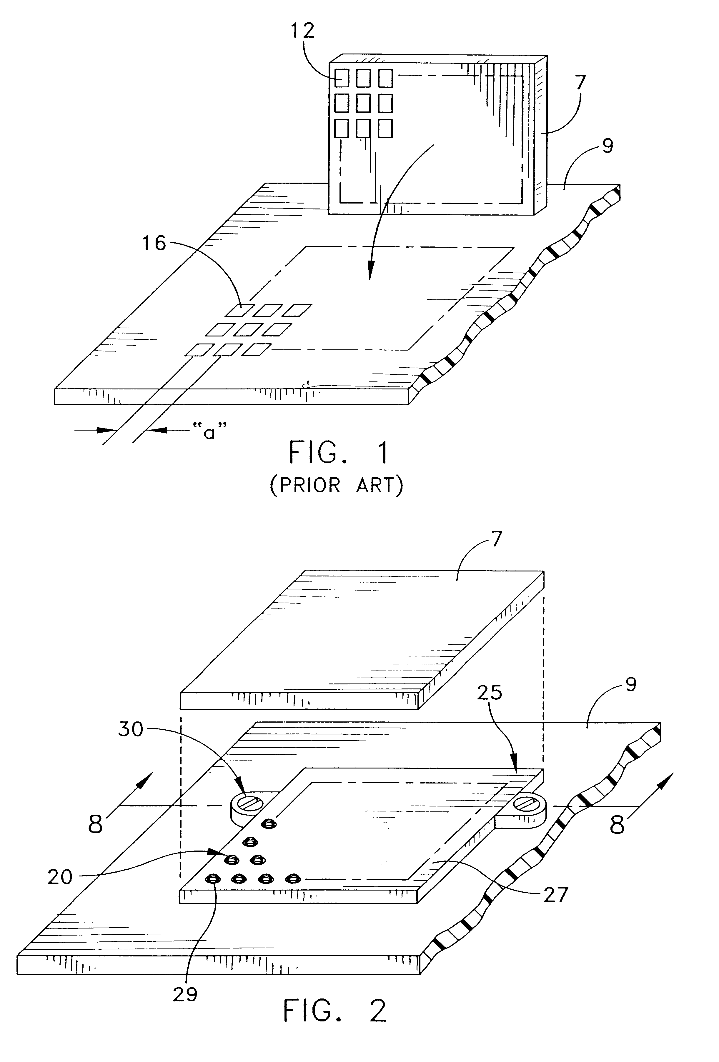
The present invention provides an electrical contact comprising a first member having spring properties and a second member wrapped around at least a portion of the first member wherein the second member has a greater electrical conductivity than the first member. In one embodiment, a conductor is wrapped around at least a portion of a spring. In another embodiment, the spring is formed into a coil or helix with a wire wrapped around at least a portion of the helical spring. In one form of this embodiment, the spring has a plurality of turns and the wire is wrapped around at least two of the turns. In another form of this embodiment, the spring has a plurality of turns and the wire is wrapped around all of the turns. An interposer connector is also provided having a frame including a top surface and a bottom surface and a plurality of apertures arranged in a pattern and opening onto the top and bottom surfaces of the frame. A plurality of springs are provided with each spring having a conductor wrapped around at least a portion of the spring where the conductor has a greater electrical conductivity than the spring. One of the springs is positioned within each of the apertures so that at least a portion of each of the conductors is exposed above the top and bottom surfaces of the frame.

Description

FIELD OF THE INVENTIONThe present invention generally relates to the electrical interconnection devices in general, and more particularly to contacts that are at the electrical interface between an integrated circuit package and a substrate or between an electrical connector and the same.BACKGROUND OF THE INVENTIONHigh density integrated circuit (IC) packages that house LSI / VLSI type semiconductor devices are well known. Input / output pins for such IC packages are often arranged in such a dense pattern (sometimes more than two hundred closely spaced contacts) that direct soldering of the IC package to a substrate, such as a printed wiring or circuit board (PCB) creates several significant problems related to inspection and correction of any resulting soldering faults.Land grid array (LGA) connectors are known for interconnecting IC packages to PCB's. LGA's typically do not require soldering procedures during engagement with the PCB. Referring to FIG. 1, prior art LGA assemblies are u...

Claims


Application Information

Patent Timeline
IPC IPC(8): H01R13/24H01R13/22H01L23/32H01R12/71H01R12/00
CPCH01R13/2407H01R13/2492H01R12/57H01R12/52G01R1/06722H01R13/2421H01R12/71
Inventor LI, CHE-YU
Owner HIGH CONNECTION DENSITY INC
Learn More