Magnetic-disc unit with gap between disc and shroud

a magnetic disc and shroud technology, applied in the direction of maintaining the head carrier alignment, recording information storage, instruments, etc., can solve the problem of disc flutter, achieve the effect of preventing disc flutter from increasing, and enhancing the degree of positional accuracy

Inactive Publication Date: 2003-12-16
WESTERN DIGITAL TECH INC +1
View PDF21 Cites 22 Cited by
  • Summary
  • Abstract
  • Description
  • Claims
  • Application Information

AI Technical Summary

Benefits of technology

An object of the present invention is to provide a rotary recording apparatus which can, on one hand, prevent flutter causing errors in positioning from increasing even though the rotational speed becomes higher, and which can, on the other hand, enhance the degree of positional accuracy for coping with a large storage capacity.
That is, according to the present invention, there is provided a large capacity magnetic disc unit which can reduce a fluid force serving as an excitation source so as to prevent occurrence of flutter in order to restrain occurrence of noise or the like, and which can read and write data from and onto a disc with a high degree of accuracy. Specifically, a shroud (outer wall) is provided around the entire periphery of a rotating disc, except an insertion part thereof for a carriage arm, and a gap between the shroud and the outer periphery of the disc is set to be not less than 0.1 mm but not greater than 0.6 mm.
An air stream induced during rotation of a disc causes a pressure differential between the upper and lower surfaces of the disc, which causes excitation of the disc, resulting in flutter of the disc. If the gap between the shroud and the disc is set to be narrower than a predetermined value, air on the upper and lower surfaces of the disc is isolated so as to reduce the pressure differential.
With this arrangement, it is possible to reduce the amplitude of flutter, and accordingly, the degree of accuracy for positioning a magnetic head even in a high speed recording apparatus can be enhanced.

Problems solved by technology

An air stream induced during rotation of a disc causes a pressure differential between the upper and lower surfaces of the disc, which causes excitation of the disc, resulting in flutter of the disc.

Method used


Image

  • Magnetic-disc unit with gap between disc and shroud
  • Magnetic-disc unit with gap between disc and shroud
  • Magnetic-disc unit with gap between disc and shroud

Examples


Embodiment Construction

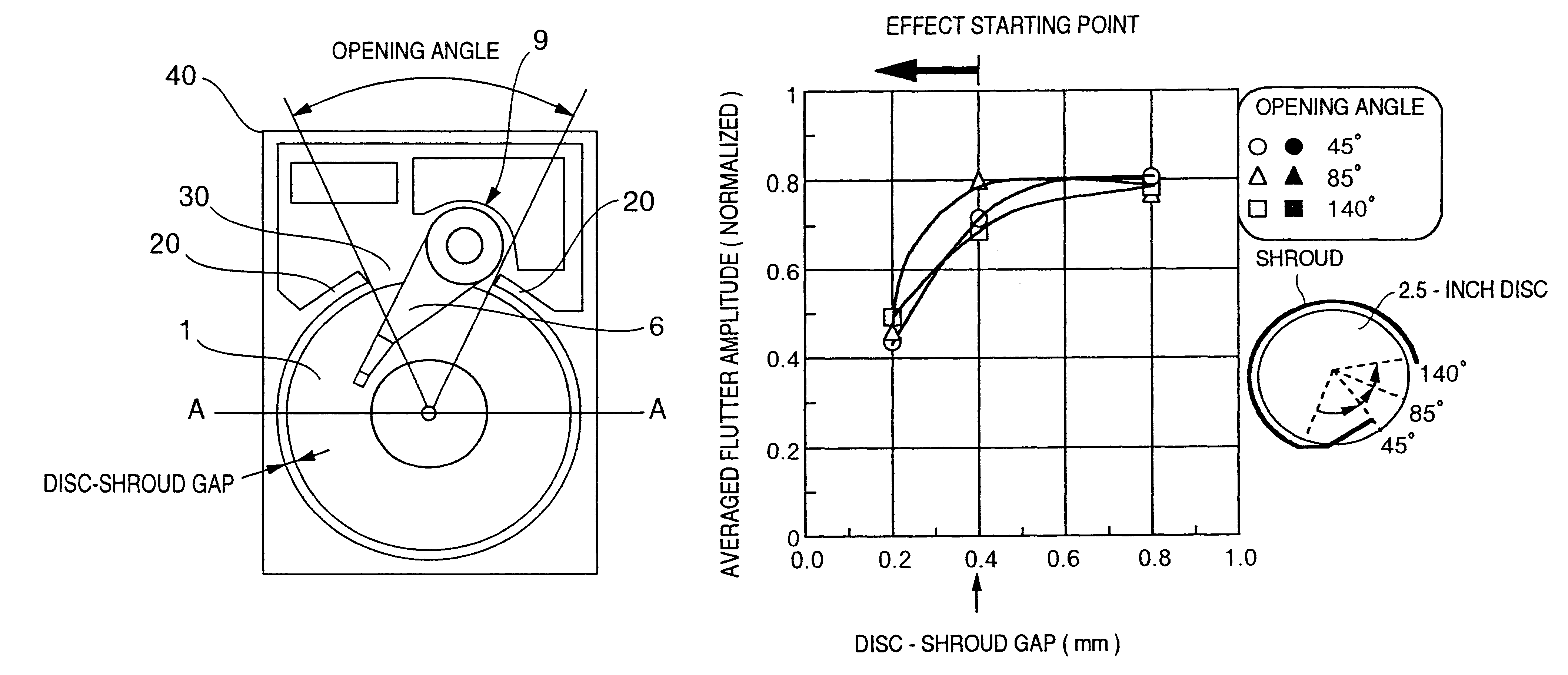
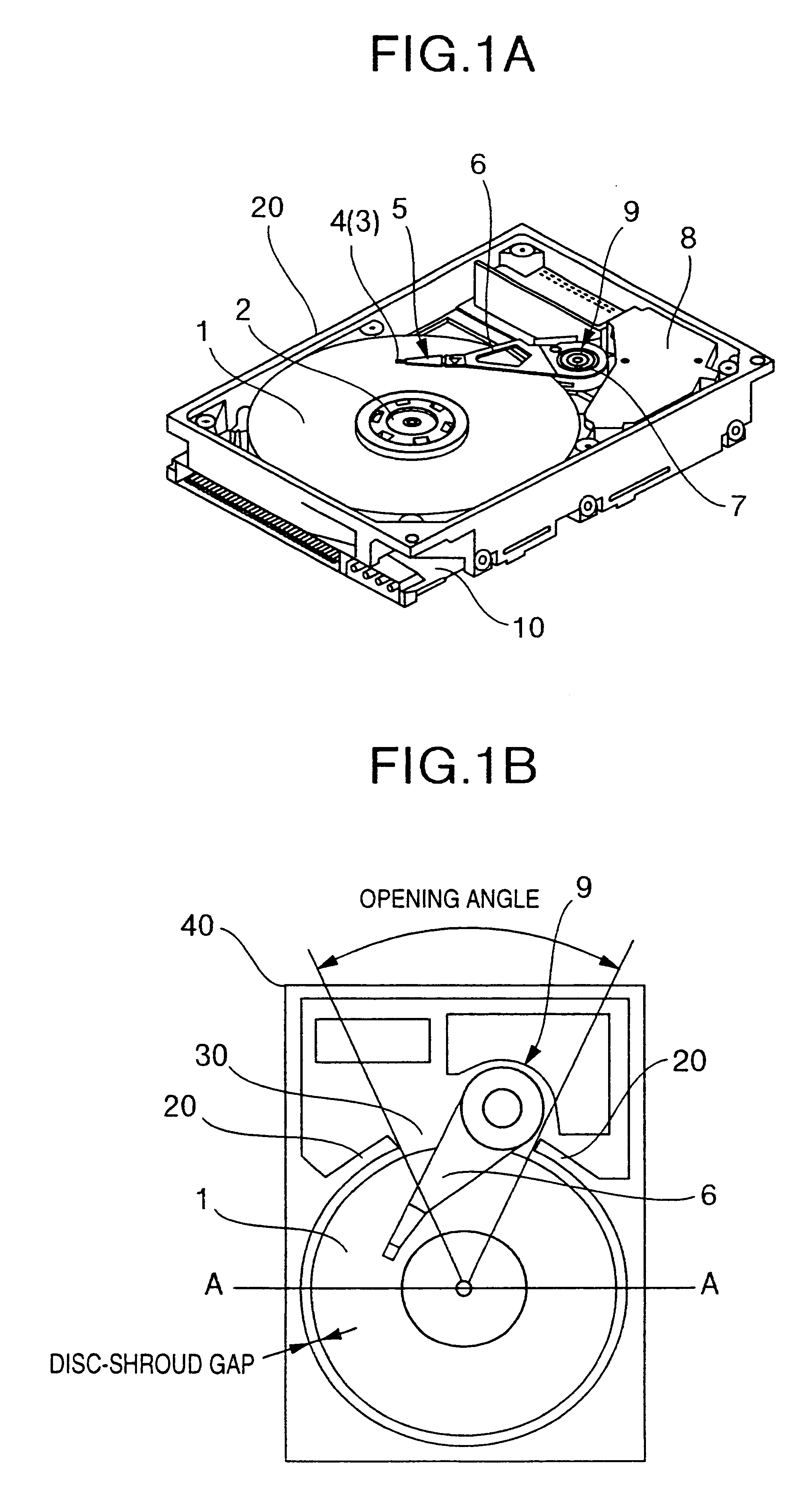
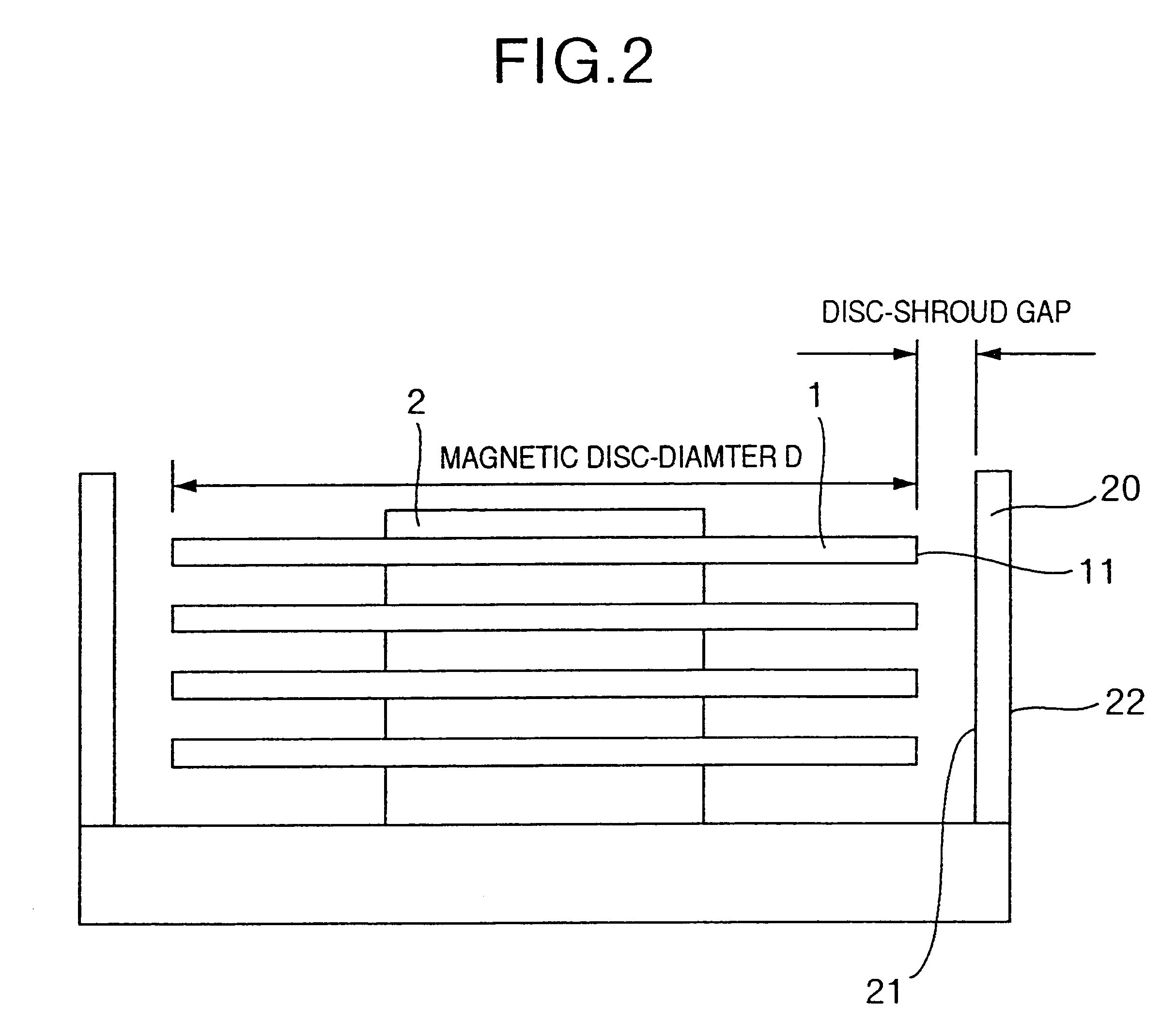
Explanation will be made of a first embodiment of the present invention with reference to FIGS. 1a to 4d. Referring to FIGS. 1A and 1B, discs 1 are stacked on a spindle 2, and a magnetic head 3 for recording and reproducing data is carried on a slider 4 which is supported by a magnetic head support mechanism 5 connected to a guide arm 6. A carriage 9 is composed of the guide arm 6, a pivot bearing 7 and a voice coil motor (which will be hereinbelow referred to as "VMC") 8, and the guide arm 6 is rotated by the VMC 8 around the pivot bearing 7. Further, these elements are set on a casting base 10 which is surrounded by a wall (shroud 20). A gap between the outer peripheries of the discs 1 and the inner wall of the shroud 20 is maintained at a predetermined distance (which will b4 referred to as "disc-shroud gap"). The shroud 20 and the base 10 are made of the same casting material, being integrally incorporated with each other.

The shroud 20 is formed therein with an opening 30 for in...


PUM

PropertyMeasurementUnit
outer diameteraaaaaaaaaa

Abstract

In a magnetic disc apparatus including a plurality of magnetic discs mounted on a spindle, arms supporting magnetic heads, a rotary actuator for the arms, and a housing having an arcuate-shaped shroud, the improvement wherein gaps between the shroud and the sides of outer peripheries of the magnetic discs are larger than 0.1 mm and less than 0.6 mm. An open space is located, downstream of the arms with respect to the air flow on surfaces of the magnetic discs, the open space being devoid of the shroud. An opening is provided in the shroud, upstream of the arms with respect to the air flow and having a greater width than a width of the gaps defined between the magnetic discs and the shroud, and a bypass channel is provided which communicates between the opening and open space.

Description

The present invention relates to a rotary recording apparatus for reading and writing data from and to a rotating disc by means of a magnetic head, an optical head or the like, and in particular to a magnetic disc unit which can reduce fluid oscillation induced on a rotating disc so as to carry out positioning with a high degree of accuracy.It a magnetic disc unit, these days, it is required to increase the capacity of memory by increasing the processing speed, and accordingly, the rotational speed of a disc has been gradually increased. However, an increase in the rotational speed, increases disc oscillation due to a fluid force caused by rotation so as to raise a new problem that the degree of positioning accuracy is lowered.Conventionally, as disclosed in Japanese Laid-Open Patent No. S59-72680, a shroud is provided around the outer periphery of a disc with a predetermined gap between the disc and the shroud in order to reduce bounce (which well be hereinbelow referred to as "flu...

Claims


Application Information

Patent Timeline
Patent Type & Authority Patents(United States)
IPC IPC(8): G11B33/08G11B33/14G11B25/04G11B5/60
CPCG11B5/6005G11B33/1446G11B33/08G11B25/043
Inventor TOKUYAMA, MIKIOSHIMIZU, HAYATOIMAI, SATOMITSUSAEGUSA, SHOZOSEGA, MASAHIKOOKAZAKI, TOSHIHISAYAMAGUCHI, YUZOIWAKURA, MASAONAKAMURA, SHIGEOSAKAI, KAZUOTOGASHI, SHIGENORIKAIHO, MASAYUKIKOBARI, TOSHIAKI
Owner WESTERN DIGITAL TECH INC
Why Eureka
Try Eureka