Plasma display panel manufacturing method for achieving luminescence characteristics

a technology of display panels and luminescence characteristics, which is applied in the manufacture of electric discharge tubes/lamps, gas exhaustion means, tube/lamp factory adjustment, etc., and can solve the problems of reducing the luminous intensity, deteriorating the luminescence characteristics, and reducing the use of phosphors

Inactive Publication Date: 2003-12-23
PANASONIC CORP
View PDF15 Cites 19 Cited by
  • Summary
  • Abstract
  • Description
  • Claims
  • Application Information

AI Technical Summary

Benefits of technology

The PDP subjected to the aging process further includes a structure in which one part of each of the outermost partitions among the plurality of partitions is connected with one part of the sealing glass layer to prevent discharge gas from flowing into space between the outermost partitions and the sealing glass layer.
The PDP subject to the aging process further includes a structure in which one part of each of the outermost partitions among the plurality of partitions and one part of the barrier are connected to prevent discharge gas from flowing into space between the outermost partitions and the barrier.
In this kind of structure, discharge gas mainly flows through a plurality of gas passages leading from the first to the second space leading from the first space to the second space, and is designed so that discharge gas can flow more freely into gas passages being used as discharge spaces than into other gas passages. This prevents deterioration in the phosphors during the aging process.
In order to achieve the above object, a PDP manufacturing process is further performed in the following way. First, a front plate and a back plate, on at least one of which discharge electrodes have been arranged and on at least one of whose inner surfaces a phosphor layer has been formed are sealed together so that an inner space is formed between them. Then a heating process for heating phosphors in the phosphor layer is performed after the aging process has been completed. This heating process enables the characteristics of the phosphors to be restored.
By using the above manufacturing method to restrict deterioration caused in particular to the blue phosphor, a PDP with superior luminescence characteristics can be obtained. Specifically, a PDP in which a color temperature of light emitted when all of the cells are ignited by applying the same power to each cell is 7000K can be obtained.

Problems solved by technology

However, in the PDP manufacturing process used in the related art, a particular problem is posed by the fact that the aging process for stabilizing the luminescence and discharge characteristics actually causes a deterioration in the luminescence characteristics.
One reason for this is the deterioration in the phosphors used.
Thee compound BaMgAl.sub.10 O.sub.17 :Eu used as a blue phosphor is particularly prone to deterioration during the aging process, resulting in a decrease in luminous intensity and a deterioration in luminescent chromaticity.
If the whole panel is heated using an oven, the panel cannot be heated at a temperature higher than the softening point of the glass used to seal the front and back plates of the panel together.

Method used


Image

  • Plasma display panel manufacturing method for achieving luminescence characteristics
  • Plasma display panel manufacturing method for achieving luminescence characteristics
  • Plasma display panel manufacturing method for achieving luminescence characteristics

Examples


first embodiment

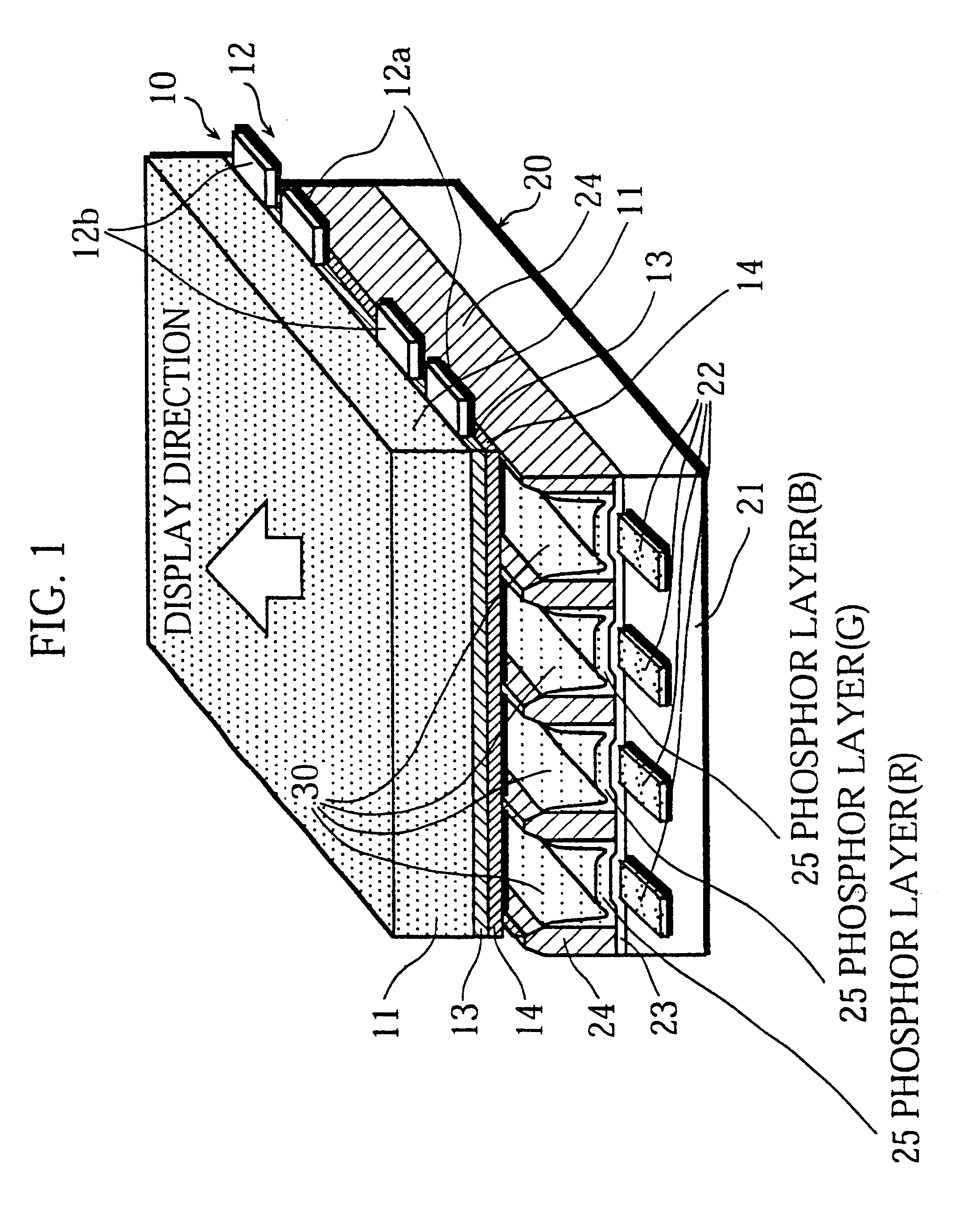
FIG. 1 is a cross-section showing the essential components of an AC PDP relating to the present embodiment. In the drawing, a part of the display area in the center of the PDP is shown.

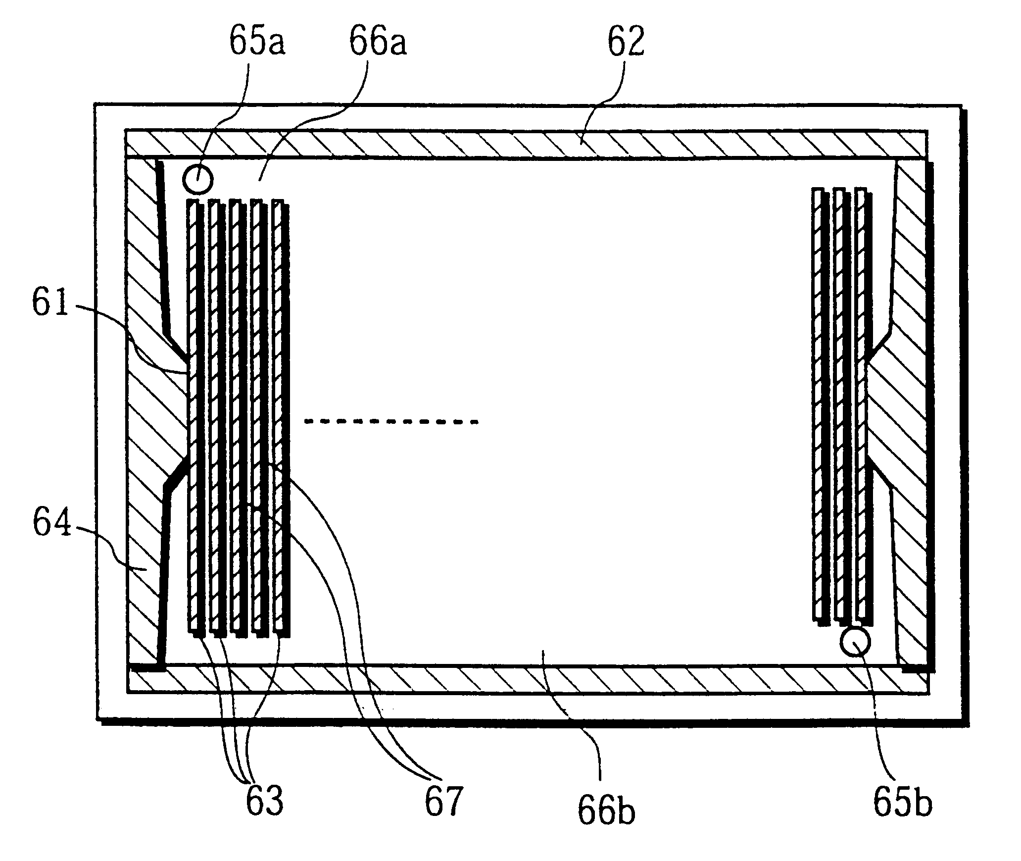
This PDP is constructed from a front plate 10 and a back plate 20. The front plate 10 is formed from a front glass plate 11, on whose inward surface are placed discharge electrodes 12, formed of pairs of scanning electrodes 12a and sustaining electrodes 12b, a dielectric layer 13 and a protective layer 14. The back glass plate 20 is formed from a back glass plate 21, on whose inward surface are placed address electrodes 22 and a visible light reflective layer 23. The front plate 10 and the back plate 20 are arranged in parallel leaving a gap between them, with the discharge electrodes 12 and the address electrodes 22 facing each other. The space between the front plate 10 and the back plate 20 is divided into discharge spaces 30 by constructing partitions 24, which run in uniform parallel lines. A dis...

second embodiment

In this embodiment, the aging process and subsequent processes differ from those in the first embodiment, but the structure of the PDP and the manufacturing method used are identical, so that only those points unique to this embodiment will be explained here.

In the present embodiment, after the front and back plates have been sealed, the aging process is performed under the conditions normally prevailing in the related art. This method is a simple one, in which a pulse discharge is applied between discharge electrodes to generate a discharge. However, in this conventional aging process, heat deterioration in the phosphors as described above causes a marked deterioration in the luminous intensity and discharge characteristics to occur. This embodiment aims to effectively restore the deterioration in the luminescence characteristics caused to the phosphor layer during the aging process.

With this aim in mind, the following additional processes are performed in the present embodiment af...


PUM


Abstract

The object of this invention is to provide a plasma display panel in which an aging process essential to the manufacturing process generates minimal phosphor deterioration, enabling a relatively high luminous efficiency and high quality color production to be produced. To achieve this object, the aging process takes place while gas generated inside the panel is evacuated. Alternatively, after completion of the aging process, the phosphor of the whole panel is heated to restore heat deterioration.

Description

INDUSTRIAL FIELD OF USEThe present invention relates to a manufacturing method for a plasma display panel used to display images on computer monitors, televisions and the like.RELATED ARTThe following is an explanation of a display panel in the related art with reference to the drawings. FIG. 21 is a simplified cross sectional of an alternating current (AC) plasma display panel (hereafter referred to as a PDP).In FIG. 21, discharge electrodes 211 are formed on a front glass plate 210. These are then covered by a layer of dielectric glass 212 and a protective dielectric layer 213, composed of magnesium oxide (MgO). A description of this technique may be found in Japanese Laid-Open Patent No. 5-342991.Address electrodes 221 are formed on a rear glass plate 220, and covered by a visible light reflective layer 222 and partitions 223. A phosphor layer 224 is placed on top of this. Spaces 230 are discharge spaces which enclose a discharge gas. Three types of phosphors, for producing the c...

Claims


Application Information

Patent Timeline
Patent Type & Authority Patents(United States)
IPC IPC(8): H01J9/44H01J17/49
CPCH01J9/445H01J11/54H01J11/48H01J11/12H01J11/42H01J9/241
Inventor KADO, HIROYUKIOHTANI, MITSUHIROAOKI, MASAKI
Owner PANASONIC CORP
Why Eureka
Try Eureka