Magnetic resonance angiography using floating table projection imaging

a technology of magnetic resonance and projection imaging, applied in the field of magnetic resonance imaging, can solve the problems of radial streak artifacts from outside entering the local fov, and achieve the effects of sacrificing image quality, high time resolution, and high spatial resolution

Inactive Publication Date: 2003-12-30
WISCONSIN ALUMNI RES FOUND
View PDF14 Cites 43 Cited by
  • Summary
  • Abstract
  • Description
  • Claims
  • Application Information

AI Technical Summary

Benefits of technology

Yet another object of the invention is to obtain higher time and spatial resolution images while tracking a contrast bolus through a subject's vasculature. By using a projection reconstruction method for acquiring image data, a higher time resolution can be achieved without significantly sacrificing image quality. This enables reconstruction of CEMRA images with optimal contrast enhancement in each subregion.

Problems solved by technology

However, radial streak artifacts from outside can enter the local FOV.

Method used


Image

  • Magnetic resonance angiography using floating table projection imaging
  • Magnetic resonance angiography using floating table projection imaging
  • Magnetic resonance angiography using floating table projection imaging

Examples


Embodiment Construction

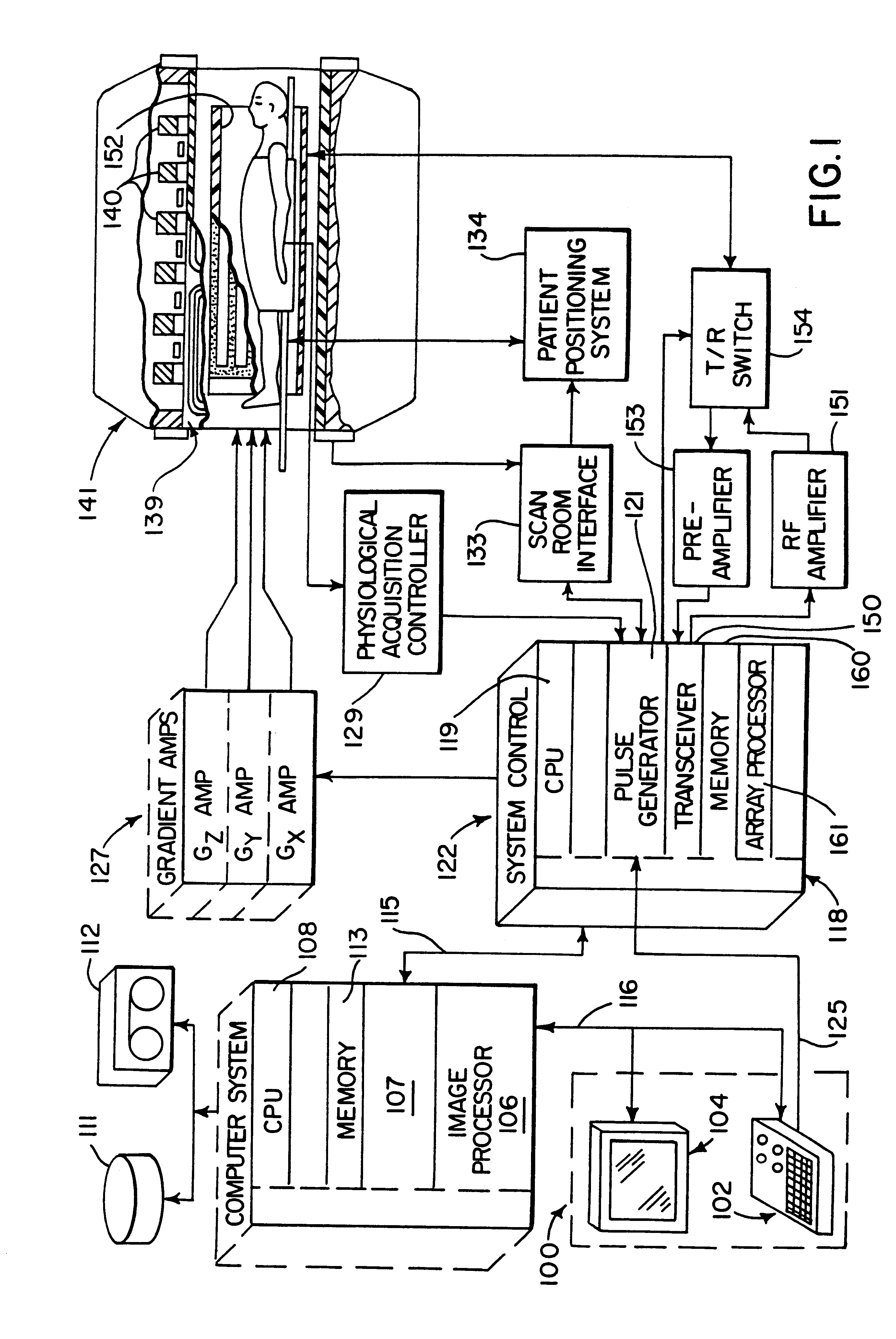
Referring first to FIG. 1, there is shown the major components of a preferred MRI system which incorporates the present invention. The operation of the system is controlled from an operator console 100 which includes a keyboard and control panel 102 and a display 104. The console 100 communicates through a link 116 with a separate computer system 107 that enables an operator to control the production and display of images on the screen 104. The computer system 107 includes a number of modules which communicate with each other through a backplane. These include an image processor module 106, a CPU module 108 and a memory module 113 for storing image data arrays. The computer system 107 is linked to a disk storage 111 and a tape drive 112 for storage of image data and programs, and it communicates with a separate system control 122 through a high speed serial link 115.

The system control 122 includes a set of modules connected together by a backplane. These include a CPU module 119 and...


PUM


Abstract

A 3D projection reconstruction pulse sequence is employed to acquire CEMRA data as the subject is continuously moved through the field of view of the MRI system. The acquired k-space data is phase corrected to offset the table motion and the corrected data is used to reconstruct an image over a field of view that far exceeds the size of the MRI system field of view. In one embodiment the image is formed as a set of anatomic subregion images which are concatenated to form a single image and in another embodiment a series of images of each anatomic subregion are produced to depict the dynamic inflow of contrast agent.

Description

BACKGROUND OF THE INVENTIONThe field of the invention is magnetic resonance imaging ("MRI"), and particularly, studies which extend over a field of view which is larger than the static field of view of the MRI system. One such study is magnetic resonance angiography of human vasculature using contrast agents.Magnetic resonance angiography (MRA) uses the nuclear magnetic resonance (NMR) phenomenon to produce images of the human vasculature. When a substance such as human tissue is subjected to a uniform magnetic field (polarizing field B.sub.0), the individual magnetic moments of the spins in the tissue attempt to align with this polarizing field, but precess about it in random order at their characteristic Larmor frequency. If the substance, or tissue, is subjected to a magnetic field (excitation field B.sub.1) which is in the x-y plane and which is near the Larmor frequency, the net aligned moment, M.sub.z, may be rotated, or "tipped", into the x-y plane to produce a net transverse...

Claims


Application Information

Patent Timeline
Patent Type & Authority Patents(United States)
IPC IPC(8): G01R33/54G01R33/563G01R33/28A61B5/055
CPCG01R33/28G01R33/56375Y10S128/922
Inventor MISTRETTA, CHARLES A.
Owner WISCONSIN ALUMNI RES FOUND
Why Eureka
Try Eureka