Tool for friction stir welding

a technology of friction stir welding and tool, which is applied in the direction of auxillary welding devices, soldering devices, forging/pressing/hammering apparatus, etc., can solve the problems of workpiece metal overheating, the pin of the tool has a tendency to break, and the workpiece metal has a tendency to overheat, so as to reduce the cost of friction, reduce the fatigue of rotary bending, and high joint efficiency

Inactive Publication Date: 2004-01-13
EDISON WELDING INSTITUTE INC
View PDF28 Cites 88 Cited by
  • Summary
  • Abstract
  • Description
  • Claims
  • Application Information

AI Technical Summary

Benefits of technology

It is another object of the present invention to provide a friction stir welding tool that decreases the cost of the friction .stir welding process.
It is yet another object of the present invention to provide a friction stir welding tool that results in high joint efficiency.
In order to meet these objects, the present invention of a friction stir weld tool comprises a cylinder having a first end for attachment to a rotating drive, a longitudinal axis, a shoulder, and a shoulder face that is substantially perpendicular (normal) to the longitudinal axis. An integral probe (tip) projects from the shoulder face with an axis that is co-extensive with the cylinder axis. The invention features an integral transition geometry structure between the shoulder face and the probe that has the advantage of substantially reducing rotary bending fatigue and subsequent breakage of the tool. Typically the transition geometry structure is a curved transition geometry structure that typically has a radius of curvature of at least about 0.040 inches+0.015(t-0.010).sup.1.5 where t is the length of the probe from its base to its distal end.
Another feature of the invention is the selection of a tool material on the basis of mechanical properties such as the ultimate tensile strength at the processing temperature of the work piece material rather than at...

Problems solved by technology

Although tool speeds of 7-15 inches/minute (180-380 mm/min are common in 1/4 inch (6 mm) aluminum-alloy stock (BS6082; U.S. Pat. No. 5,460,317), the pin of the tool has a tendency to break as the travel speed or the thickness and/or hardness of the material to be joined increases.
However, this brings about its own problems.
At such slow speeds, the workpiece metal overheats and a dramatic loss in joint efficiency, often of the order of 10-15%, occurs.
In addition, the welding process may become so slow as to be economically infeasible.
Although tool speed and breakage problems are decreased, material handling time and cost increase substantially and the technique may not be applicable where the workpiece configuration prevents access to the second side.
However,...

Method used


Image

  • Tool for friction stir welding
  • Tool for friction stir welding
  • Tool for friction stir welding

Examples


Embodiment Construction

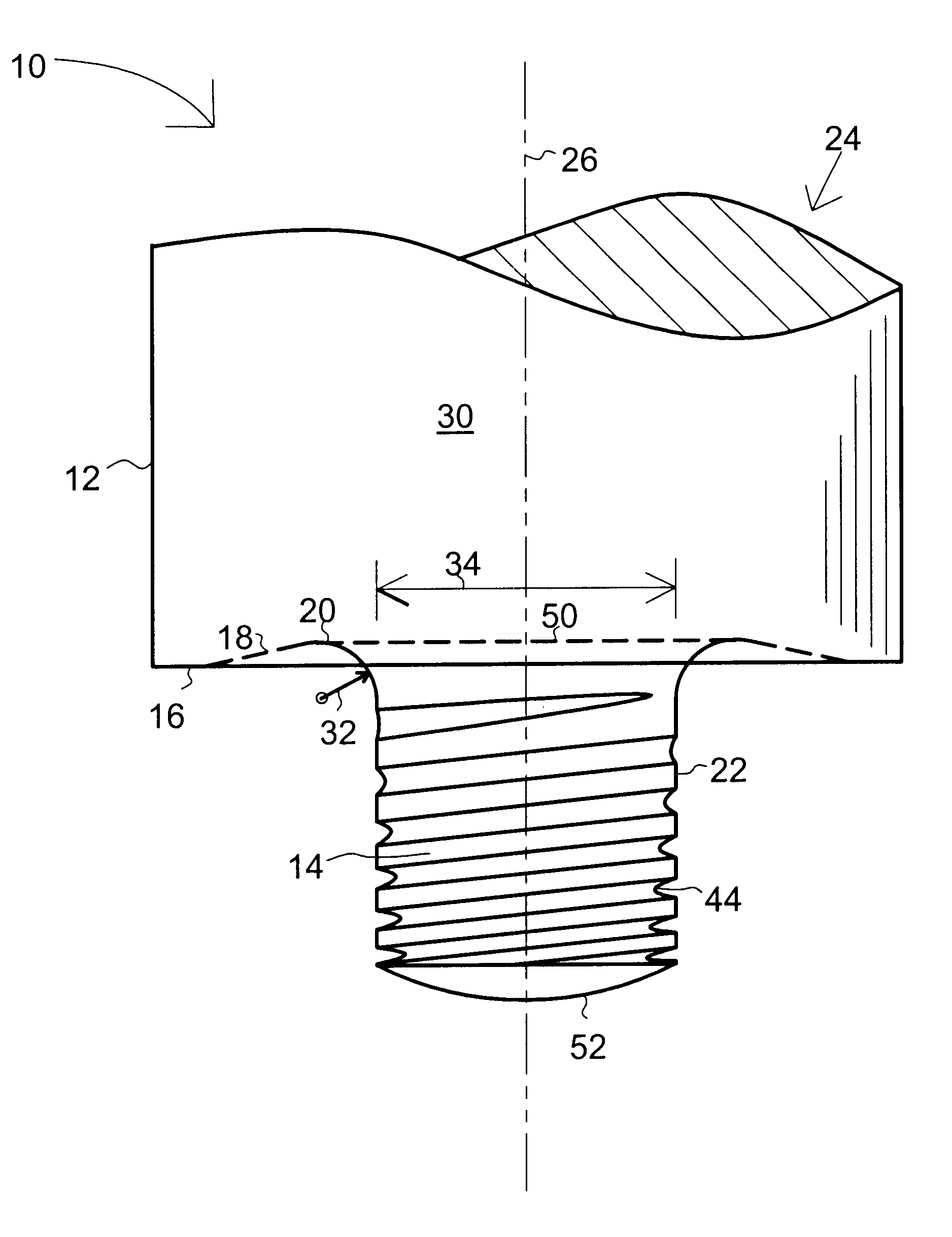
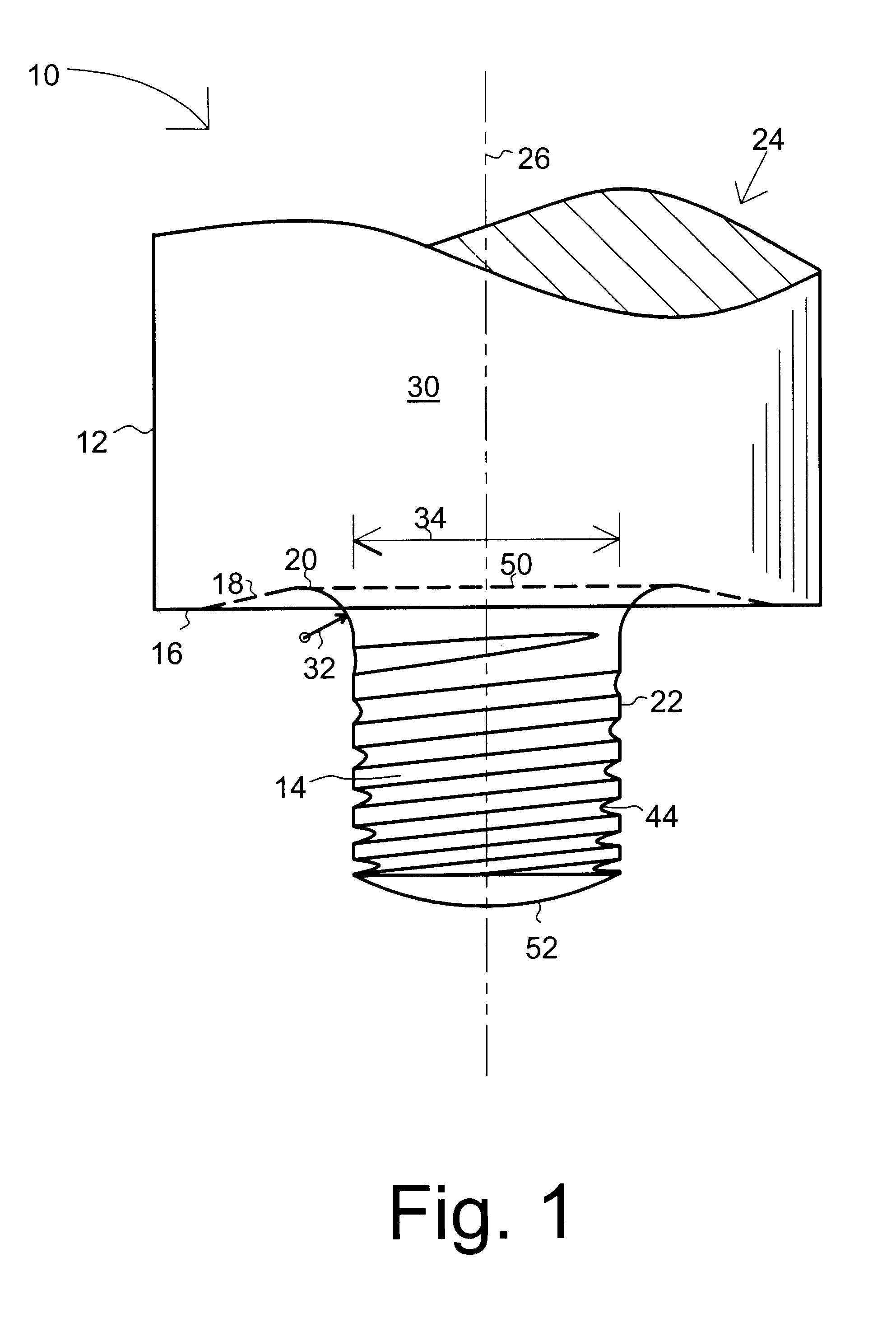
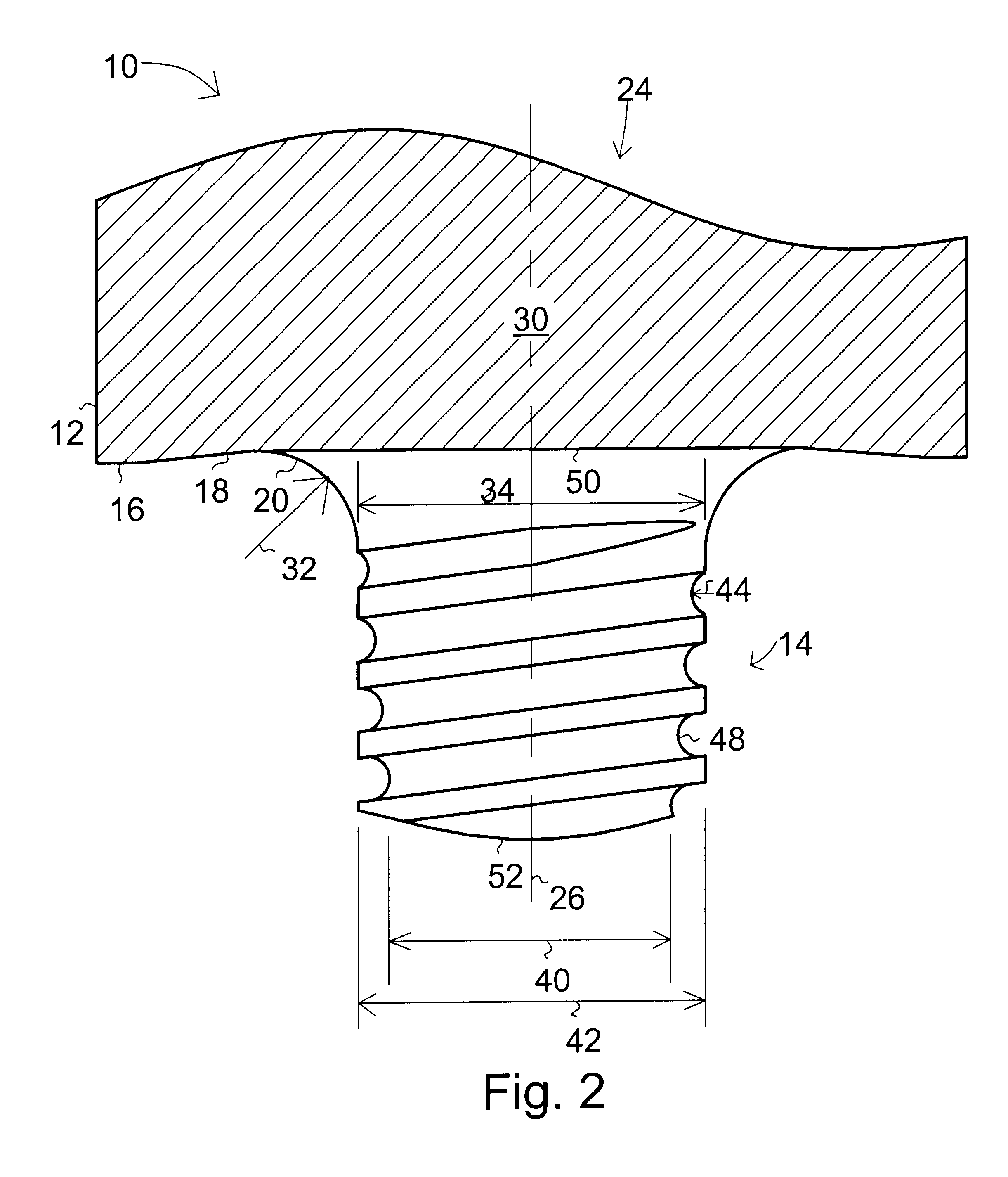
With reference to the drawings and initially FIGS. 1 and 2, a friction stir welding tool 10 is shown having a cylinder 30 with a first end 24 for attachment to a rotating drive for rotation about longitudinal axis 26, a shoulder 12, and a shoulder face 16 opposite first end 24. A probe (tip) 14 projects at a substantially right angle to the shoulder face 18 and is integral with shoulder 12. Probe 14 has a longitudinal axis that is co-extensive with the cylinder axis 26. The present invention contemplates a wide variety of probe shapes and styles including but not limited to threaded, un-threaded, cylindrical, truncated cone, reverse truncated cone, and bossed probes and various combinations thereof.

The present invention features the addition of a transition geometry region 20 at the intersection of the shoulder face 16 and base 50 of probe 14 has been found to significantly increase the operational life of tool 10. When combined with other new features such as a tapered thread root ...


PUM

PropertyMeasurementUnit
Temperatureaaaaaaaaaa
Diameteraaaaaaaaaa
Structureaaaaaaaaaa

Abstract

A friction stir welding tool for welding high-strength materials with one or more of the following features: 1) a curved transition geometry structure at the shoulder face and probe interface; 2) a tool material selected on the basis of an ultimate tensile strength determined at or above the temperature of the tool processing temperature; 3) a compressive stress at the point of crack fatigue introduced by mechanical or chemical means; and 4) a threaded probe with a) a major to minor thread diameter ratio that increases toward the distal end of the probe and/or b) with a curved thread root.

Description

1. Field of the InventionThis invention pertains to friction stir welding and more particularly to a friction stir weld tool with an improved probe structure for welding high-strength aluminum alloys and other hard materials such as steel, copper, nickel, titanium and their alloys.2. Background and Objects of the InventionFriction stir welding is a relatively new welding technique discovered in the mid, 1990s that was developed primarily for welding aluminum and soft aluminum alloys that were difficult to weld using traditional welding techniques. The technique uses a rotating shouldered cylindrical tool with a projecting pin to generate heat in the workpiece. The mechanical friction of the rotating tool contacts the workpiece and plasticizes (softens) the metal as it is plunged into the bondline. At this stage, there is a substantial amount of plasticized metal in a column about the rotating pin beneath the shoulder of the cylinder portion of the tool. The tool is then moved along ...

Claims


Application Information

Patent Timeline
IPC IPC(8): B23K20/12
CPCB23K20/1255Y10T29/49321
Inventor TRAPP, TIMOTHY J.STOTLER, TIMOTHYSKILLITER, MATHEWMOHR, WILLIAM C.HUNT, MARK L.
Owner EDISON WELDING INSTITUTE INC
Why Eureka
Try Eureka