Lock assembly with self retained barrel lock

a barrel lock and lock assembly technology, applied in the field of lock assemblies, can solve the problems of the current use of barrel locks, the complexity of installation, and the loss of locks, and achieve the effect of not affecting the effect of manufacturing costs

Inactive Publication Date: 2004-02-03
INNER TITE A DIV OF YARA ENG
View PDF25 Cites 69 Cited by
  • Summary
  • Abstract
  • Description
  • Claims
  • Application Information

AI Technical Summary

Benefits of technology

The present invention proceeds from the realization that contrary to conventional wisdom, it is not necessary to specially configure the lock barrels, or to employ extra lock components, in order to temporarily retain the barrel locks in a retracted unlocked position. Instead, this function can be assigned to the locking balls of a standard barrel lock acting in concert with an appropriately configured and positioned internal recess in a standard lock collar. By doing do, manufacturing costs are not adversely impacted, and users are not saddled with the problems associated with maintaining and employing an inventory of different barrel locks.

Problems solved by technology

There are several problems with the manner in which barrel locks are currently employed.
This complicates installation and can lead to locks being misplaced or lost.
Secondly, a key must be employed to assemble the locks with their associated lock components.
This requires widespread distribution of keys to installation personnel, which in turn increases the danger that keys will be lost or stolen, thereby seriously compromising overall system security.
A decided drawback with these arrangements, however, has been the perceived need on the part of those skilled in the art to specially machine and configure the lock barrels to mechanically interengage in the unlocked position with other components of the lock assembly.
Thus, at the manufacturing level, costs are disadvantageously increased by the need to specially machine and configure the lock barrels, and / or to incorporate extra components into the lock assembly.
At the user level, where conventional lock assemblies and barrel locks are already in use, the introduction of barrel locks with specially configured barrels requires both types of locks to be maintained in inventory for use by installation and maintenance personnel, thus disadvantageously complicating the overall administration of a security system.

Method used


Image

  • Lock assembly with self retained barrel lock
  • Lock assembly with self retained barrel lock
  • Lock assembly with self retained barrel lock

Examples


Embodiment Construction

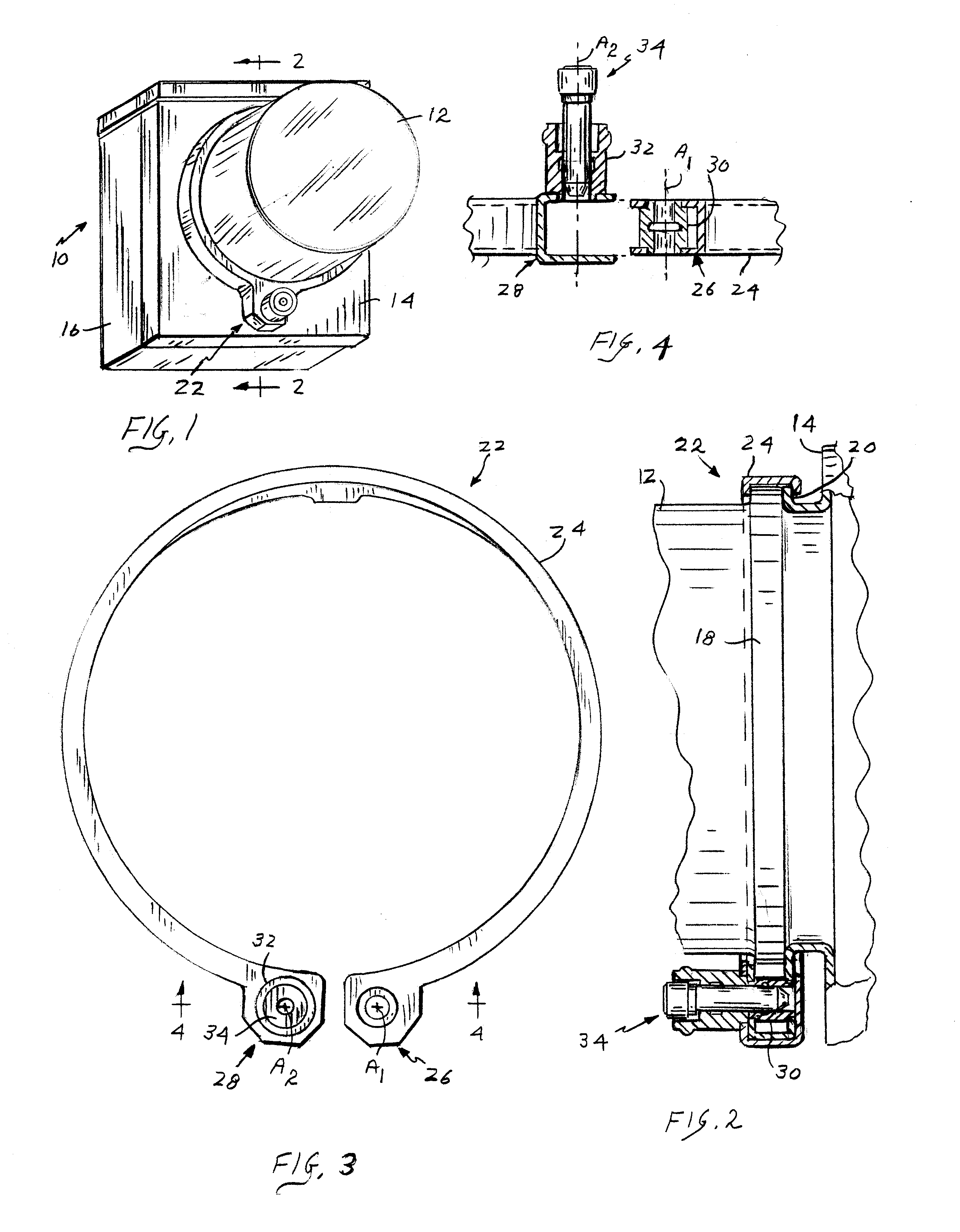
Referring initially to FIGS. 1 and 2, a utility meter employing a split retaining ring incorporating a lock combination in accordance with the present invention is generally depicted at 10. The metering mechanism (not shown) is enclosed by a glass cover 12 removably mounted to the lid 14 of a box-shaped housing 16. The cover and lid are provided respectively with confronting circular rims 18, 20. A split retaining ring 22 is employed to secure the rims 18, 20 in an axially aligned abutting relationship.

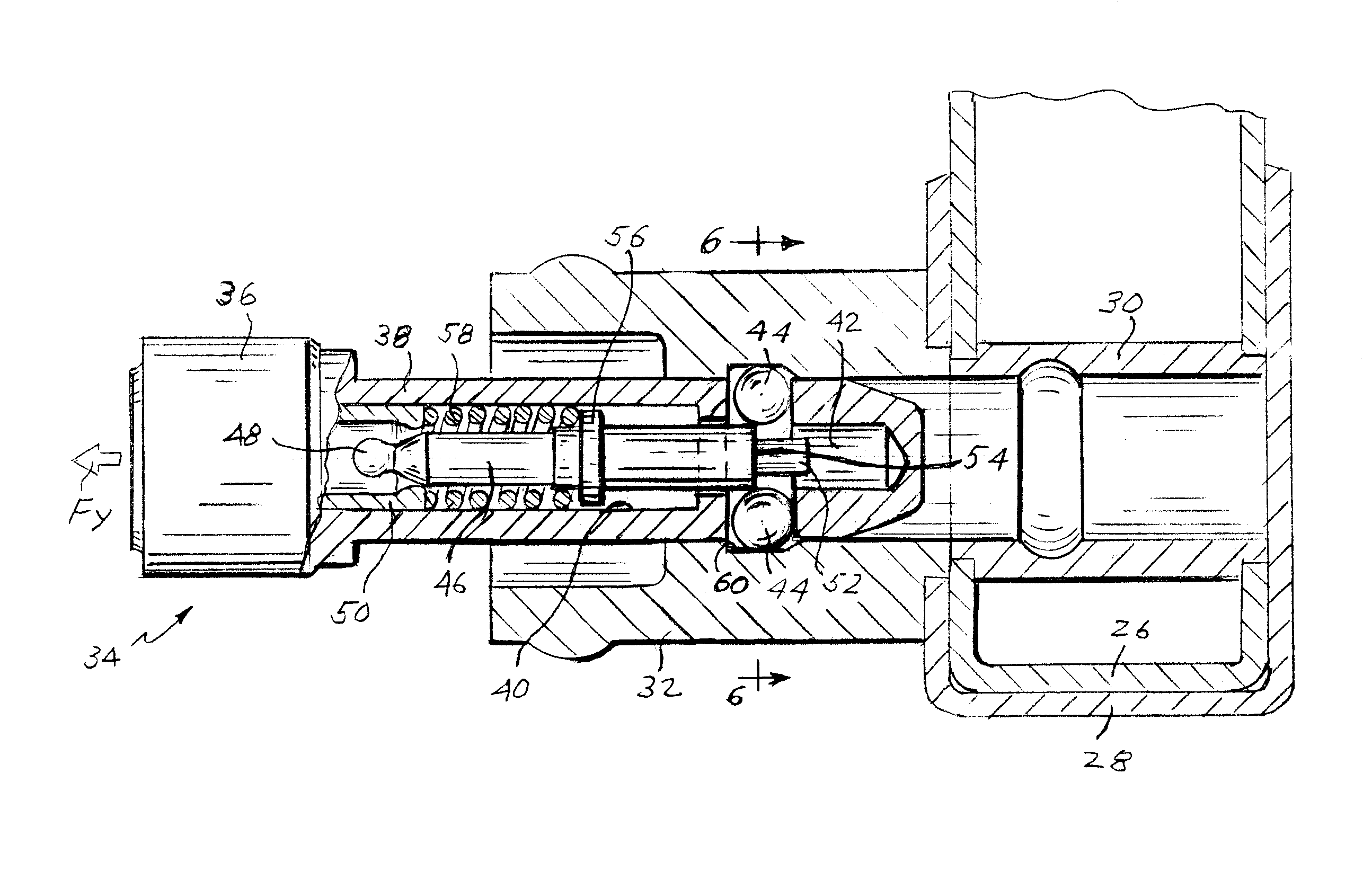
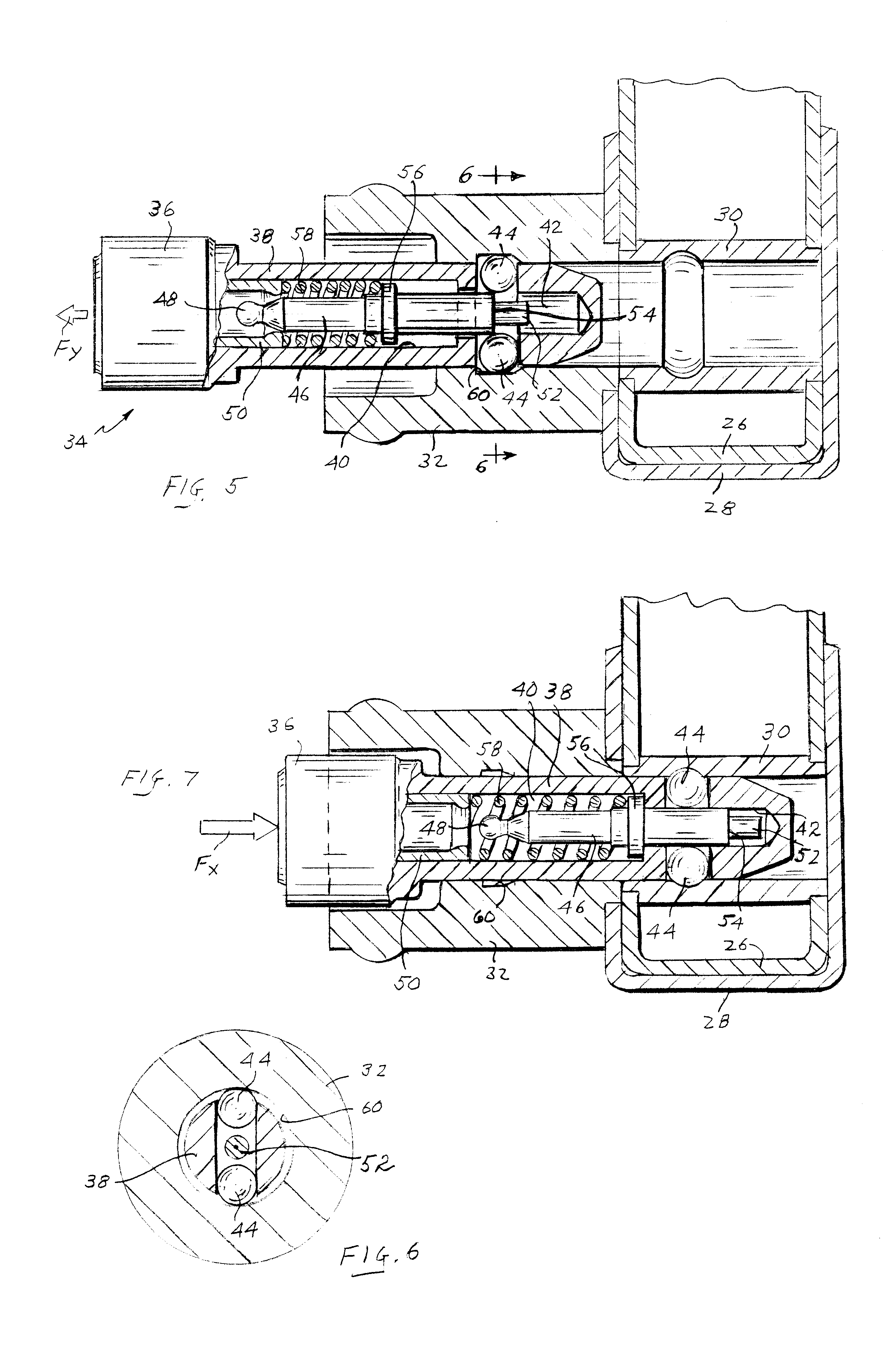
With reference additionally to FIGS. 3 and 4, it will be seen that the split retaining ring 22 has a generally channel-shaped side wall 24 curving from a male end 26 to a female end 28. A bushing 30 is contained in the male end 26, and an exterior tubular collar 32 is secured to the female end 28. The split ring is resiliently adjustable between an enlarged condition as shown in FIGS. 3 and 4, which accommodates its installation on and removal from the rims 18, 20, and a constricted c...


PUM


Abstract

A security device comprises a first component having a through first passageway surrounded by an internal first recess, and a second component having a second passageway surrounded by an internal second recess. The first and second components are configured for assembly in a mating relationship with the first and second passageways in communication with each other and in coaxial alignment. A lock has a barrel containing a spring and plunger and carrying radially shiftable locking elements, with the plunger being normally biased by the spring in one direction urging the locking elements into expanded positions protruding radially from the barrel. The barrel is insertable into and releasably retained in an unlocked position in the first passageway with the locking elements expanded radially outwardly into the first recess, and is shiftable by a forwardly applied axial force into a locked position in the second passageway with the locking elements expanded into the second recess. The first recess has a forward surface configured to coact with the locking elements in response to the forwardly applied force to exert a reactionary force urging the locking elements radially inwardly and urging the plunger in the opposite direction to accommodate retraction of the locking elements from the first recess.

Description

1. Field of the InventionThis invention relates generally to lock assemblies incorporating barrel locks, and is concerned in particular with the self retention of the barrel locks in the lock assemblies when in the unlocked state. Such lock assemblies are widely employed by public utilities to secure meters, supply conduits, etc. against unauthorized access.2. Description of the Prior ArtThe metering mechanism of a conventional utility meter is typically enclosed within a transparent cover removably mounted to the lid of a box-shaped housing. The cover and lid have confronting circular rims which are held in an axially aligned abutting relationship by a split retaining ring in combination with a barrel lock.The split retaining ring has a generally channel-shaped side wall curving from one end containing an internal bushing to another end provided with a cylindrical external collar. The internal bushing and external collar comprise components of a lock assembly configured for use wit...

Claims


Application Information

Patent Timeline
Patent Type & Authority Patents(United States)
IPC IPC(8): E05B67/00E05B67/36E05B65/00
CPCE05B67/365E05B65/0089Y10T70/443Y10T70/40Y10T70/5566Y10T70/5841Y10T70/5872Y10T70/7751Y10T70/439Y10T70/441
Inventor AGBAY, ANTHONY J.MAHANEY, JOHN
Owner INNER TITE A DIV OF YARA ENG
Why Eureka
Try Eureka