
Method and apparatus for manufacturing composite structures

a composite material and manufacturing method technology, applied in the field of composite material structure, can solve the problems of increasing cost, adding each joint in the structure, and requiring a substantial amount of time to achieve a uniform and consistent flush join

Inactive Publication Date: 2004-02-17
BEECHCRAFT
View PDF14 Cites 300 Cited by
  • Summary
  • Abstract
  • Description
  • Claims
  • Application Information

AI Technical Summary

Benefits of technology

"This patent is about a tool and method for making composite structures, specifically aircraft fuselage components, using fiber placement techniques. The tool includes a mandrel body and a bladder that can be fitted around the mandrel body, with a caul sheet section that overlaps with the bladder. The tool can simplify the process of installing and removing the mandrel, and can allow for increased interior space in the composite structure. The technical effects of this invention include reducing the time and cost of manufacturing composite structures, and reducing the weight of the assembled components."

Problems solved by technology

From a manufacturing sense each joint in a structure tends to add cost.
Also, from a manufacturing sense each extra component or detail tends to add cost.
However, these composite structures have typically been manufactured by time consuming application methods, such as hand placement.
Machining and assembling of flush joints into a single uniform component typically requires a substantial amount of time to achieve a uniform and consistent flush joint.
In addition to extra time, each flush joint adds additional material and weight to the assembled aircraft component.
Therefore, the greater the number of separate parts required to construct a single component, such as fuselage component sections, the larger the amount of time and the greater the amount of weight added to the assembled component.
Although fiber placement processes may be used to produce composite structures of varying dimension and size more quickly and efficiently than other methods, current fiber placement techniques suffer from complications relating to mandrel construction and removal of the mandrel after fiber placement has occurred.
Segmented mandrel designs suffer from numerous problems, including expansion of the mandrel material during heat curing, leakage between mandrel segment joints, and time and effort involved in the assembly and disassembly of mandrel components.
These structures suffer from the cost and weight problems described above for other multi-piece composite structure components.

Method used


Image

  • Method and apparatus for manufacturing composite structures
  • Method and apparatus for manufacturing composite structures
  • Method and apparatus for manufacturing composite structures

Examples


Embodiment Construction

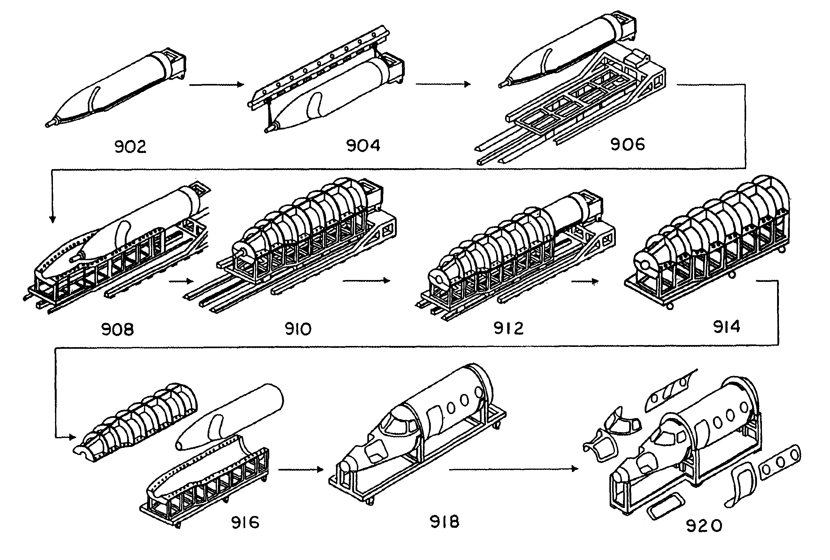
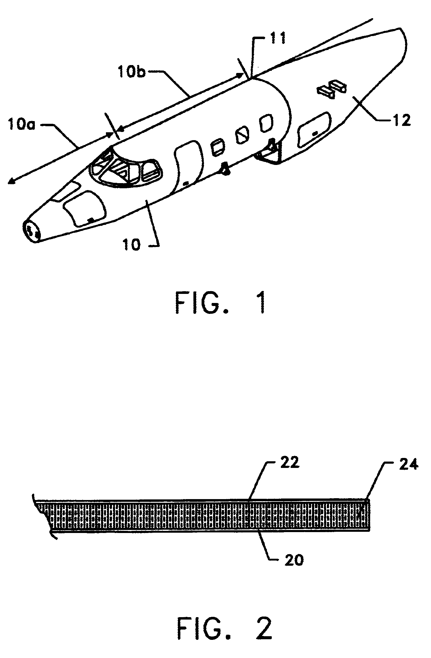
In embodiments of the disclosed method and apparatus, composite structures having high quality, light weight, and low fabrication costs are possible. These characteristics are achieved by, among other things, providing a single piece full cylinder composite structure design having no axial joints, composite shell outer surfaces which are tooled to the outer mold line, and relatively large composite structure components that reduce the number of separate components required for assembly. Furthermore, methods are provided for fabrication of composite structure shells on a tool having an outer surface representing the inside surface of the fabricated structure to achieve minimum labor content.

Various embodiments of the disclosed method and apparatus are directed to structural designs, manufacturing processes, and tooling systems capable of producing composite structures at minimum cost and weight. In a typical embodiment, this disclosure is directed to fabrication of aircraft fuselage ...


PUM

PropertyMeasurementUnit
diameteraaaaaaaaaa
lengthaaaaaaaaaa
lengthaaaaaaaaaa

Abstract

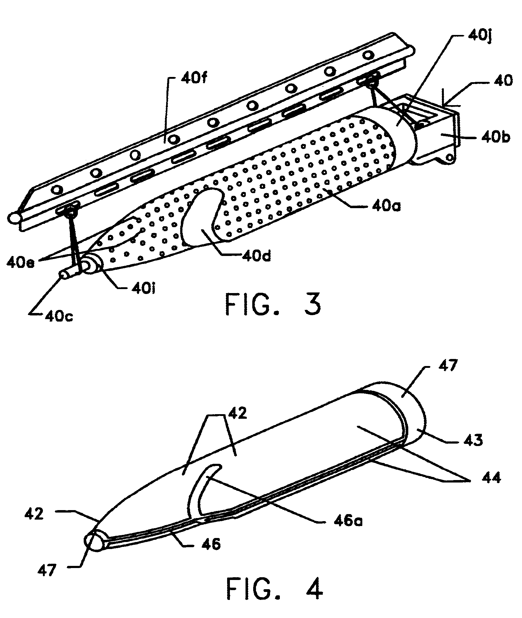
Composite structures having a single continuous skin may be formed using automated fiber placement methods. These composite structures include frameless aircraft fuselage components offering an increased interior cabin width over conventional fuselage components. The composite structures may be constructed of multiple layers of fibers and other materials placed on a fiber placement tool that includes a mandrel body surrounded by a bladder or an integral bladder / caul sheet having expansion spaces created within the caul sheet section. Uncured composite structures may be created by placing fibers around the fiber placement tool in a plurality of discontinuous segments that are capable of moving or sliding in relation to each other so that the uncured composite structure is expandable from within. Fluid openings may be provided in the outer surface of the mandrel body for the application of vacuum and / or fluid pressure to secure the bladder to the mandrel body and to assist in the removal of the bladder from the mandrel body, respectively. Uncured composite structures may be sealed between the bladder and is clam shell molds. The uncured structures may be expanded against the inner surface of the molds by creating a vacuum between the bladder and molds.

Description

1. Field of the InventionThis invention relates generally to composite material structures and, more specifically, to fiber placement methods and apparatus for manufacturing composite material shells. In particular, this invention relates to composite material shells, such as aircraft fuselage components, formed using fiber placement and other methods employing a removable mandrel and a bladder with or without an integral caul sheet.2. Description of the Related ArtThe fuselage of an airplane or other similar vehicle is generally a thin shell of revolution. In the case of an airplane, one of the significant loading conditions for a fuselage is circumferential tension resulting from internal pressure. Structurally it is most efficient to carry this loading with a structure having a continuous diameter or hoop without any axial joints. From a manufacturing sense each joint in a structure tends to add cost. Also, from a manufacturing sense each extra component or detail tends to add co...

Claims


Application Information

Patent Timeline
Patent Type & Authority Patents(United States)
IPC IPC(8): B29C43/56B29C43/10B29C43/12B29C43/32B29C70/04B29C70/44B29C70/34
CPCB29C43/12B29C43/56B29C70/342B29C70/44B29C70/46B29C2043/3649B29C2043/3655B29C2043/562B29L2031/3082B29C70/549
Inventor LUNDE, GERALD A.
Owner BEECHCRAFT
Learn More