Thermal transfer recording apparatus and thermal transfer recording method using the same

a recording apparatus and thermal transfer technology, applied in thermography, duplicating/marking methods, instruments, etc., can solve the problems of difficult image registration, no other substrate can be selected, and high cost of substrates, and achieve the effect of high speed

Inactive Publication Date: 2004-03-09
PANASONIC CORP
View PDF20 Cites 15 Cited by
  • Summary
  • Abstract
  • Description
  • Claims
  • Application Information

AI Technical Summary

Benefits of technology

When the image is recorded continuously using the thermal transfer recording apparatus of the present invention, the dye receiving layers which have been cut and transferred are positioned in series at a substantially constant spacing on the intermediate record support in a region between the downstream of the dye receiving layer transfer section and the upstream of the image transfer section. This makes high speed and continuous printing possible. For example, when recording of an A6 size image which is positioned transversely (or transverse A6 size recording) is carried out at a rate of 5 ms / line using line recording heads each having a resolution of 300 dpi as the dye receiving layer transfer head and the image transfer head, it takes 30-40 seconds to obtain the first print. However, when the thermal transfer recording is carried out continuously, one print can be obtained within ten seconds, so that 24 prints can be obtained within four minutes.

Problems solved by technology

Therefore, the thermal transfer recording method has a disadvantage in that the substrate, which is expensive, is to be used as the image receiver, and no other substrate can be selected.
However, the dye receiving layer supporting sheet is made of the thin sheet-form substrate and the image is formed on the dye receiving layer on such a sheet-form substrate by thermally transferring the dye, so that the first re-transfer recording method has problems in that registration of the image is difficult and in that it is not always easy to handle the dye receiving layer supporting sheet in an apparatus.
Therefore, it is difficult to control the heat upon re-transferring the dye receiving layer on which the image has been recorded to the image receiver, so that there is a problem in that it is difficult to re-transfer with stability.
However, it is difficult to control meandering of the belt, so that there is a problem in that speedy and stable thermal transfer of the recording image is difficult.
Particularly, the belt as the intermediate record support moves is an unstable fashion.

Method used


Image

  • Thermal transfer recording apparatus and thermal transfer recording method using the same
  • Thermal transfer recording apparatus and thermal transfer recording method using the same
  • Thermal transfer recording apparatus and thermal transfer recording method using the same

Examples


embodiment 1

of the Thermal Transfer Recording Apparatus

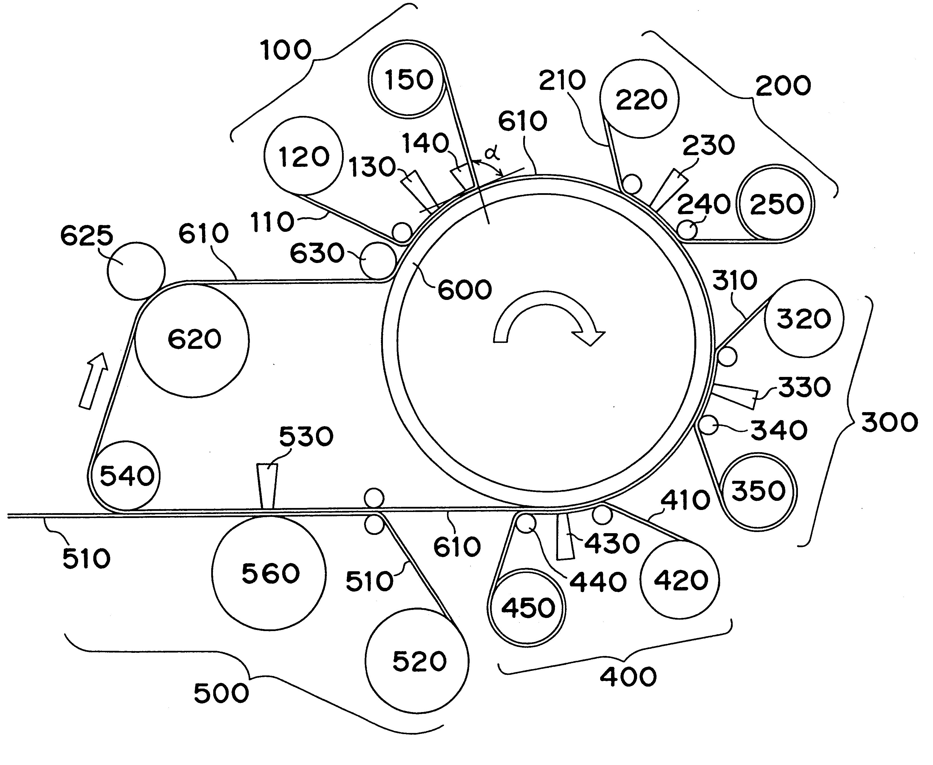
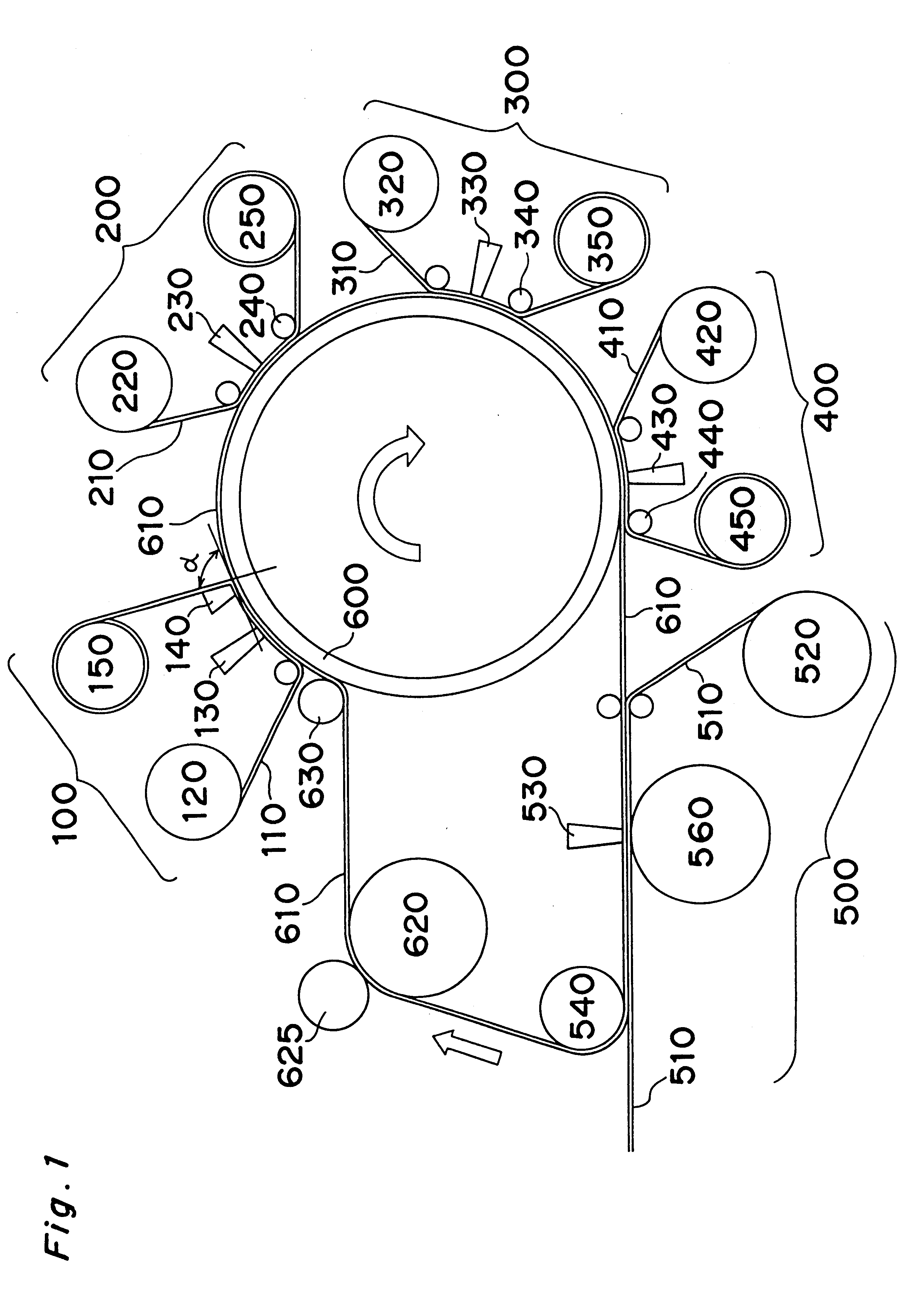
FIG. 1 shows an example of a constitution of one embodiment of the thermal transfer recording apparatus according to the present invention.

An intermediate record support 610 which forms a closed loop is placed such that the loop extends over a larger diameter drum 600 and smaller diameter drums (or rollers) 620, 630 and 540 and contacts with a roller 560 via an image receiver 510. The larger diameter drum 600 has a diameter of for example, about 200 mm, and the smaller diameter drum has a diameter of, for example, about 50 mm or less. A dye receiving layer transfer section 100 and image recording sections for three primary colors (for Y, M and C) 200, 300 and 400 are placed on an outside of the intermediate record support 610 on a part (about two thirds in the embodiment shown in FIG. 1) of the outer periphery of the larger diameter drum 600. An image transfer section 500 is placed adjacent to and downstream of the image recording section 4...

embodiment 2

of the Thermal Transfer Recording Apparatus

FIG. 5 shows an example of a constitution of another embodiment of the thermal transfer recording apparatus of the present invention.

The thermal transfer recording apparatus shown in FIG. 5 has a constitution substantially the same as that of the apparatus shown in FIG. 1 except that the smaller diameter drum 625 is removed and the dye receiving layer transfer section 100 is placed outside of the intermediate record support 610 which is on the outer periphery of the smaller diameter drum 620 as compared to in the thermal transfer recording apparatus shown in FIG. 1.

As to the intermediate record support 610, the larger diameter drum 600, the driving method for the intermediate record support 610, the dye receiving layer transfer 110, the dye transferers for Y, M and C 210, 310 and 410, the dye receiving layer transfer head 130, the image recording heads for Y, M and C 230, 330 and 430, and the image transfer head 530, etc. which are used in ...

embodiment 3

of the Thermal Transfer Recording Apparatus

FIG. 6 shows an example of a constitution of the other embodiment of the thermal transfer recording apparatus according to the present invention.

The thermal transfer recording apparatus shown in FIG. 6 has substantially the same constitution as that of the apparatus shown in FIG. 1 except that the smaller diameter drum 625 is removed, a cleaning mechanism 700 for the intermediate record support 610 is placed outside the intermediate record support 610 on the outer periphery of the smaller diameter drum 620, a smaller diameter drum 550 which contacts with the smaller diameter drum 540 is provided in the image transfer section 500, and a smaller diameter drum 640 and a meandering preventive mechanism 800 are placed upstream of the cleaning mechanism 700 and downstream of the image transfer section 500 as compared to the thermal transfer recording apparatus shown in FIG. 1.

It is noted that the smaller diameter drum 550 functions as a nip rolle...


PUM

PropertyMeasurementUnit
heat shrinkage ratioaaaaaaaaaa
elongationaaaaaaaaaa
contact angleaaaaaaaaaa

Abstract

A thermal transfer recording apparatus for recording a glossy and high quality image alleviates or substantially solves at least one of the problems of low recording speed of the image, poor stability of recording, and high running cost of recording. The thermal transfer recording apparatus has an intermediate record support which forms a closed loop and extends over a plurality of drums which are placed separately, and a dye receiving layer transfer section having a dye receiving layer transfer head which faces a part of the intermediate record support on an outer periphery of one drum of the plurality of the drums. The thermal transfer recording apparatus also has an image recording section having at least one image recording head which faces a part of the intermediate record support on an outer periphery of the one drum, and an image transfer section having an image transfer head which faces the intermediate record support inside of the closed loop.

Description

The present invention relates to a thermal transfer recording apparatus (e.g., a thermal transfer printer) and a thermal transfer recording method (e.g., a thermal transfer printing method). In particular, the present invention relates to a thermal transfer recording apparatus and a thermal transfer recording method in which a full-colored and high quality image can be formed on a plain paper at a high speed and a low cost, for example, in a digital mode.A thermal transfer recording method in which a dye is transferred by heating can provide an image having a high quality which is substantially equivalent to that of the silver halide conventional full color photograph. Furthermore, the thermal transfer recording method is an excellent recording technique which puts less of a load on the global environment and which allows instant recording (or printing) (i.e., recording can be done immediately). An apparatus for such a method is compact and excellent in its maintainability.However, ...

Claims


Application Information

Patent Timeline
Patent Type & Authority Patents(United States)
IPC IPC(8): B41J2/325B41M5/34B41J2/32B41M5/382
CPCB41J2/325B41M5/345B41M5/38257
Inventor TAGUCHI, NOBUYOSHI
Owner PANASONIC CORP
Why Eureka
Try Eureka