Method and device for detecting and compensating zero point influences on coriolis mass flowmeters

a zero-point influence, flowmeter technology, applied in the direction of mass flowmeters, liquid/fluent solid measurement, testing/calibration of volume flow, etc., can solve the problems of mass flow meter and reaction not being detected, substantial disturbance of measuring instruments, and interference, so as to improve the operational response and eliminate interference. , the effect of full measurement capacity

Inactive Publication Date: 2004-03-16
BAILEY FISCHER & PORTER
View PDF7 Cites 26 Cited by
  • Summary
  • Abstract
  • Description
  • Claims
  • Application Information

AI Technical Summary

Benefits of technology

This achieves the object of eliminating interference from the metrological response.
A further subaspect of the object, which is intended to improve the operational response, is achieved by two special configurational features according to the invention. Redundancy is provided by the two-fold determination of the flow rate. In the case of severe interference or a failure of a sensor, an evaluation section can be used to maintain full measurement capacity. However, elimination of interference no longer obtains. The control response is improved by virtue of the fact that an actual-value signal is available which is not influenced by the flow rate. A ...

Problems solved by technology

If asymmetrical signal interference now occurs in the case of which individual signal components, or else both components of the sensors change, this leads to measuring errors and control problems.
Consequently, it is possible to excite both structural and hydraulic vibrations at the operating frequency of the mass flow meter which cause reactions in the mass flow meter and are not detected by the electronic measurement system.
The interactions of these vibrations generally occur asymmetrically and can lead to substantial disturbances of the measuring instrument.
The most unfavorable consequence of these interactions are substantial disturbances of the metrological properties.
Since they feature ...

Method used


Image

  • Method and device for detecting and compensating zero point influences on coriolis mass flowmeters
  • Method and device for detecting and compensating zero point influences on coriolis mass flowmeters
  • Method and device for detecting and compensating zero point influences on coriolis mass flowmeters

Examples


example 1

No Flow Rate

FIG. 4 shows the appropriate vector diagram for this.

Sensor signals:

A=5

B=5

C=5

Calculations:

D.sub.CA =C-A=5-5=0

D.sub.CB =C.multidot.B=5-5=0

D.sub.CACB =D.sub.CA -D.sub.CB =0

S.sub.CACB =D.sub.CA +D.sub.CB =0

Result: ##EQU10##

The corresponding phasor diagram is represented in FIG. 4. The phasors, that is to say the vectors, are parallel and of equal length in this representation; the result is that: the flow rate is zero.

example 2

Non-zero Flow Rate Without Interference

FIG. 5 shows the appropriate vector diagram.

Sensor signals:

A=5-j2

B=5+j2

C=5

Calculations:

D.sub.CA =C-A=(5)-(5-j2)=0+j2

D.sub.CB =C-B=(5)-(5+j2)=0+-j4

D.sub.CACB =D.sub.CA -D.sub.CB =(j2)-(-j2)=0+j4

S.sub.CACB =D.sub.CA +D.sub.CB =(j2)+(-j2)=0+j0

Result: ##EQU11##

That is to say, in this example there is a flow rate Qm of 0.8 k.

It may be seen that the phasor diagram is symmetrical, that is to say the vibration, that is to say the phase shift, as well, resulting from the non-zero throughflow occurs symmetrically. See FIG. 5.

example 3

Throughflow, Interferer Additive to A with 180.degree. Phase Angle Relative to C

FIG. 6 shows the appropriate vector diagram.

Interference signal additive to sensor A:

St=-1

Sensor signals:

A=4-j2

B=5-j2


PUM


Abstract

A method and a device for measuring the flow rate of flowing, in particular liquid media using the Coriolis measurement principle, in which a measuring tube flowed through by the medium can be set vibrating and the deflection of the measuring tube is measured at at least two different measuring points via sensors and the flow rate can be determined from the amplitude and further vibration parameters with the aid of an electric evaluation unit. In this case, a further sensor is arranged at the site of vibration generation and the two other sensors are placed at sites which are arranged symmetrically with regard to their distance, referred to the tube section of the measuring tube, from the site of vibration generation. The evaluation unit contains logic means which, in the event of failure of one of the sensors, on the one hand report this, and on the other hand simulate the defective sensor in terms of evaluation by interpolation until the defective sensor is replaced.

Description

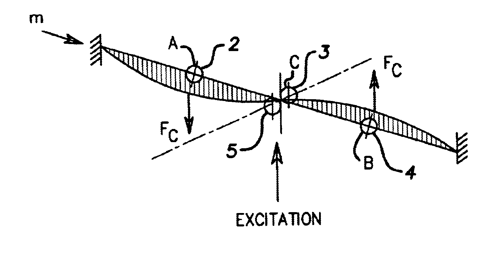
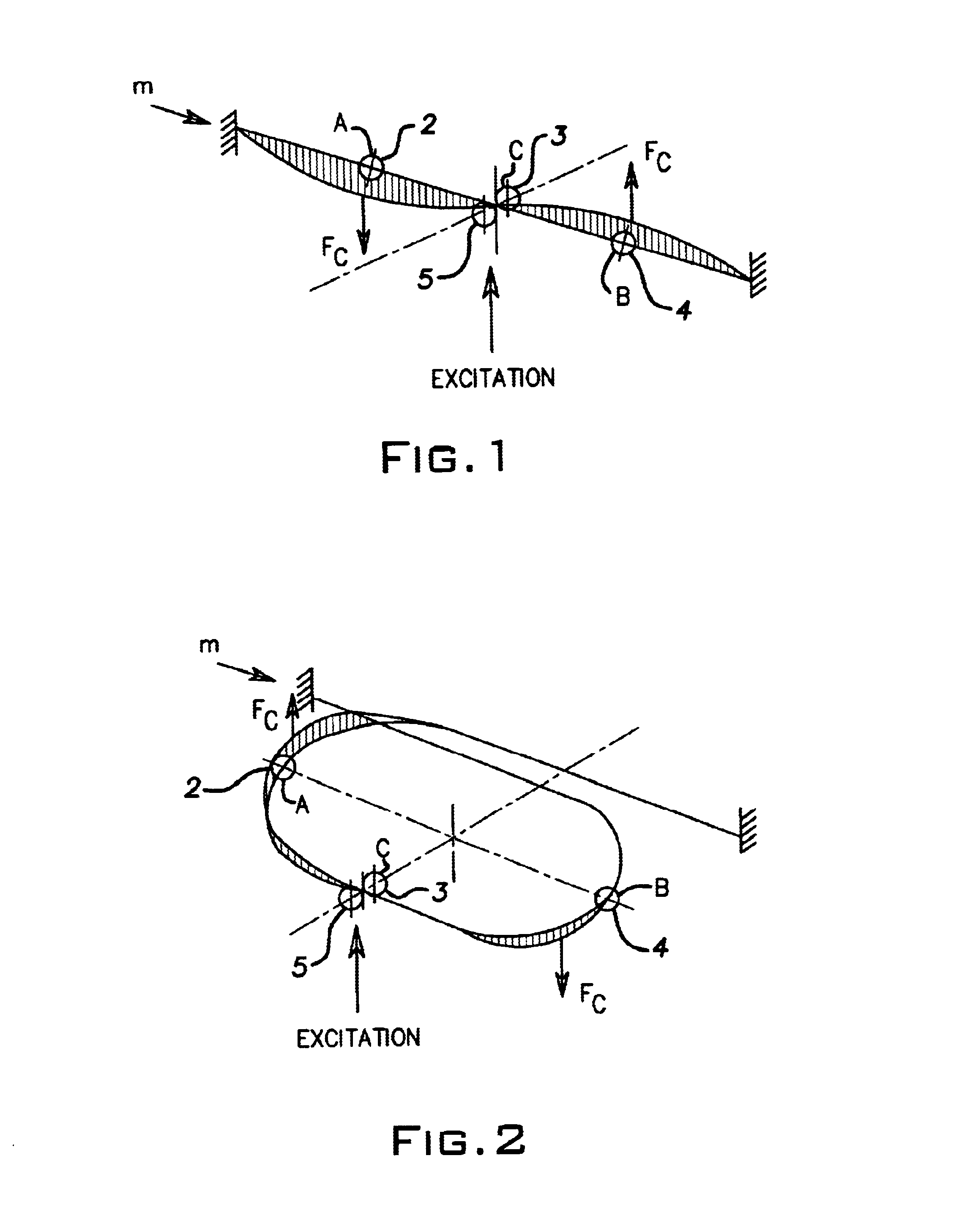
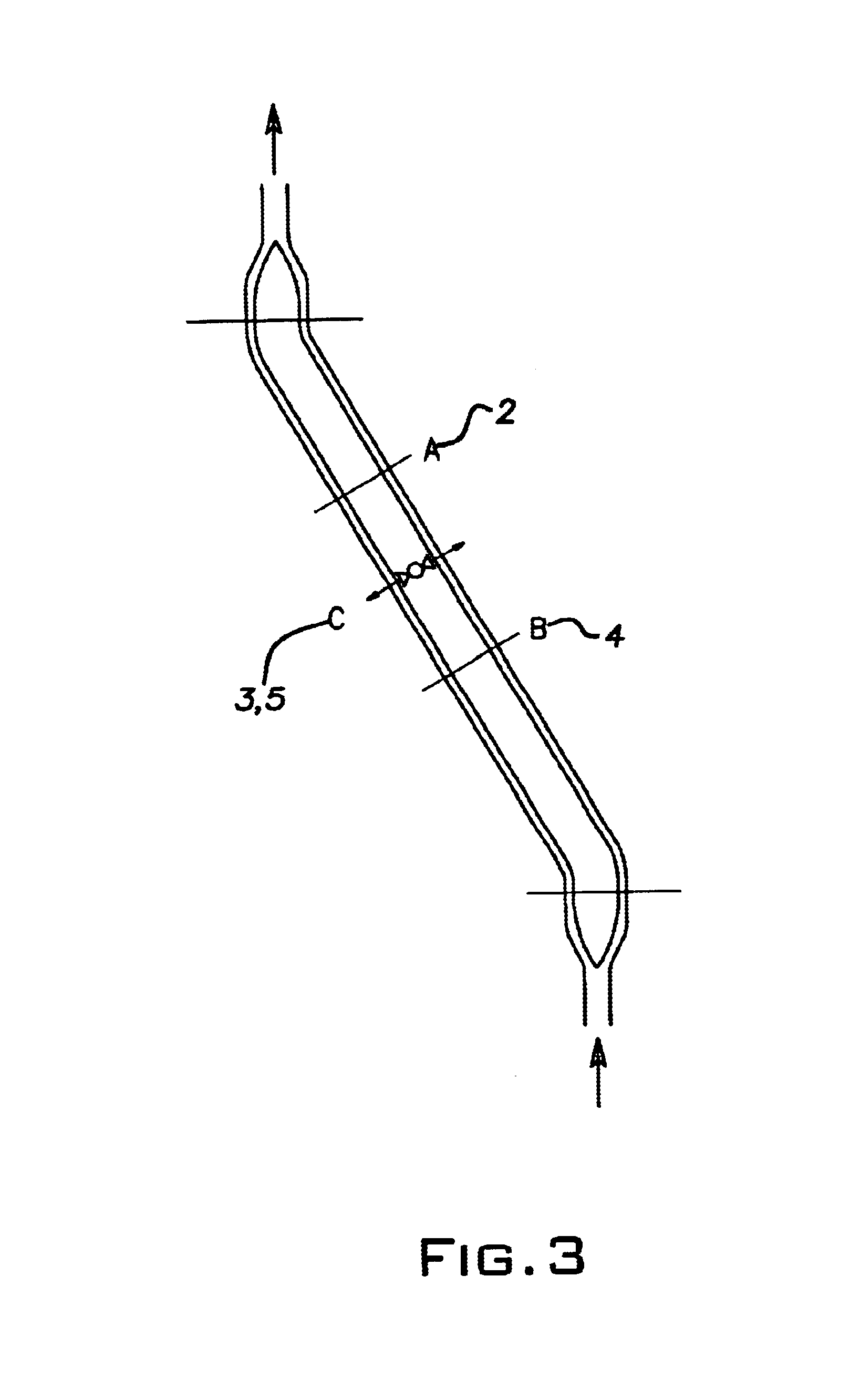
This invention relates to a method and a measuring instrument for measuring, in particular, the flow rate of flowing media using the Coriolis principle, having at least one measuring the conducting the flowing medium, at least one vibrator which sets the measuring tube vibrating, and having at least two sensors which detect the tube movement and an electronic evaluation system which processes the measuring signals.DESCRIPTION OF THE PRIOR ARTCoriolis mass flow meters for flowing media are widespread, and are known in very varied embodiments.In general, in the case of a Coriolis mass flow meter at least one measuring tube which is symmetrical relative to its geometrical midpoint is set vibrating by a vibrator. The vibration of the measuring tube is monitored in this case by a control circuit which receives its actual value information from at least one of the above-named sensors which detect the tube movement.The vibration of the measuring tube causes the Coriolis force in the flowin...

Claims


Application Information

Patent Timeline
IPC IPC(8): G01F1/84G01F1/76G01F25/00
CPCG01F1/8431G01F1/8436G01F1/8481G01F1/849G01F1/8495G01F25/0007G01F25/10
Inventor DEPPE, LOTHARLESJAK, RALFPAPENBROCK, AXEL
Owner BAILEY FISCHER & PORTER
Why Eureka
Try Eureka