Method of formation and charge of the negative polarizable carbon electrode in an electric double layer capacitor

a technology of carbon electrode and electric double layer capacitor, which is applied in the direction of capacitors, electrical equipment, protecting/adjusting hybrid/edl capacitors, etc., can solve the problems of capacitors that permit very low discharge and charge currents, low practical charge and discharge currents, and relatively low specific energy of capacitors

Inactive Publication Date: 2004-03-16
WAINWRIGHT D WALKER
View PDF10 Cites 77 Cited by
  • Summary
  • Abstract
  • Description
  • Claims
  • Application Information

AI Technical Summary

Problems solved by technology

However, a disadvantage of these capacitors is their rather low specific energy, not exceeding 3 Wh/l.
This maximum value of specific energy for double-layer capacitors is set with non-aqueous electrolytes, where the maximum voltage values are in the range of 3 to 3.5 V. However, such capacitors permit very low discharge and charge currents due to the very low conductivity of non-aqueous electrolytes.
However, a drawback of this prototype in Patent of Japan, Accepted Application No. 2-11008, is the very low practical charge and discharge current (0.1 to 1 mA/cm.sup.2) and, therefore, very low power density as a result of using a non-aqueous electrolyte.
Another essential disadvantage of the device in question is its very low cycleability--about 100-200 cycles.
However, this capacitor has a number of drawbacks, for example it contains emergency valves that make it not entirely hermetical.
The main disadvantage of the capacitors em

Method used


Image

  • Method of formation and charge of the negative polarizable carbon electrode in an electric double layer capacitor
  • Method of formation and charge of the negative polarizable carbon electrode in an electric double layer capacitor
  • Method of formation and charge of the negative polarizable carbon electrode in an electric double layer capacitor

Examples


example 1

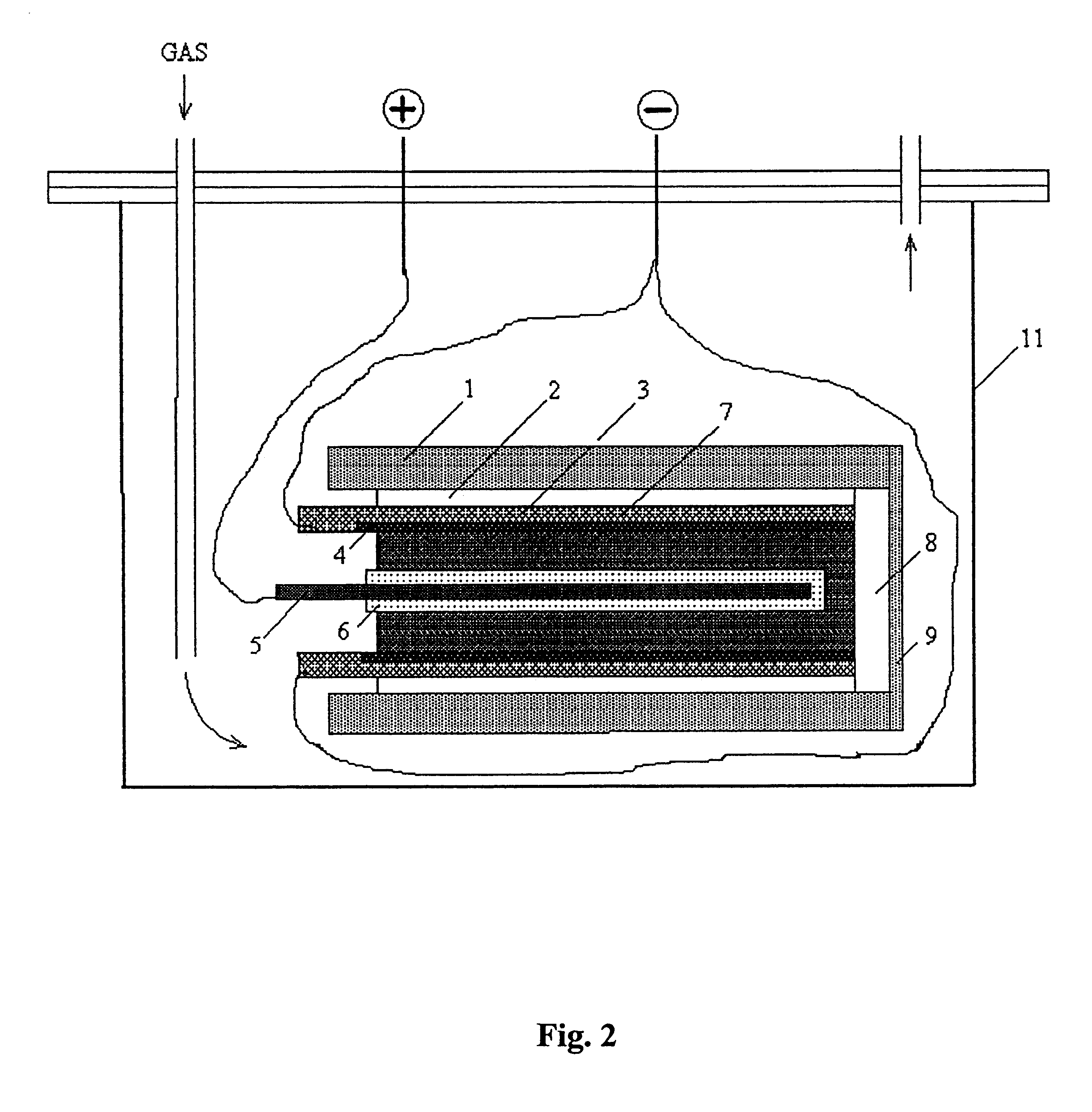
The device in use was identical to that described in the second embodiment, set forth above. The formation process differed in some cycling parameters. Three charge-discharge cycles were performed instead of one with current density of 10 mA / cm.sup.2. The end-of-charge voltage was 0.6 V, the potential of the negative electrode being 1.1 V vs. RHE; the end-of-discharge potential was -0.9 V vs. RHE. Discharge at 10 mA / cm.sup.2 followed the formation. The resulting specific capacitance of the negative polarizable electrode and specific energy of the capacitor were 790 C / g and 29.5 Wh / kg, respectively.

example 2

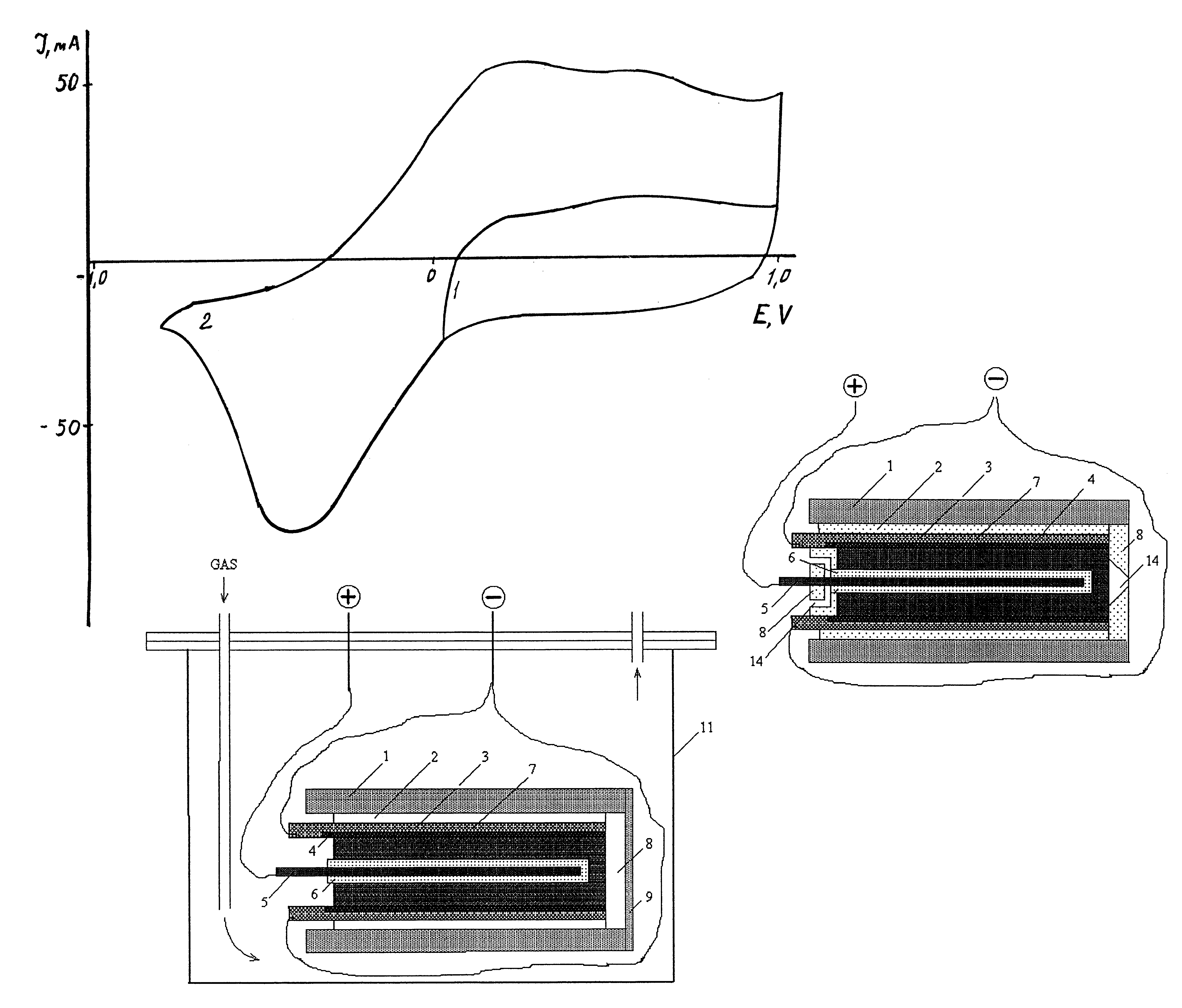
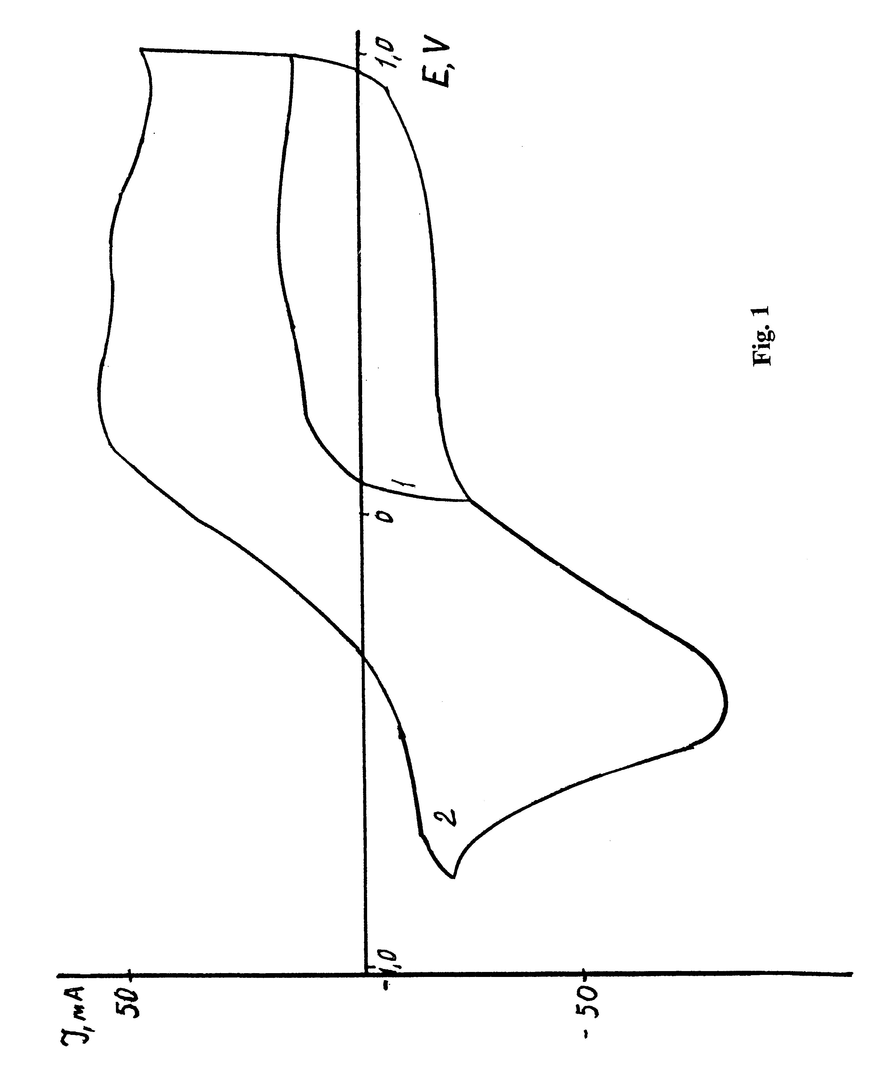
The capacitor in this example employed two electrodes made of TSA activated carbon cloth 0.3 mm in thickness, the negative consisting of a single layer, and the positive of two layers. FIG. 6 shows five voltammograms of this system obtained at scan rate of 1 mV / sec in the potential range form 1.0 V to the corresponding final values: 0 V (curve 1); -0.2 V (curve 2); -0.5 V (curve 3); -0.8 V (curve 4); and -1.0 V (curve 5). The cathode branches stand for charge, while the anode ones stand for discharge of the negative electrode. The cathode branches of curves 4 and 5 exhibit maxima at 0.55 V, curve 5 testifying on sharp increase of the current, which most probably corresponds to hydrogen evolution. Extra area and thus extra discharge capacity was obtained under the anode branches of curves 2, 3, and 4. The anode part areas of curves 4 and 5 were basically equal, which renders the discharge capacities equal as well. One can see that enlargement of the potential window by 0.8 V in the n...

example 3

The hybrid capacitor used in this example was similar to that described in Example 1 in its polarizable electrodes, but a positive electrode of the NiOOH / Ni(OH).sub.2 type was employed instead of PbO.sub.2 / PbSO.sub.4 and 30% aqueous solution of KOH served as electrolyte. A multi-step formation charge was performed as follows: at the first step (down to 0.25 V vs. RHE) the current density was 7 mA / cm.sup.2 ; at the second step (down to -0.55 V vs. RHE) the current density was 15 mA / cm.sup.2 ; at the third step the current density was kept at 7 mA / cm.sup.2 for 5 hours. Three charge-discharge cycles followed then charge as described above and finally discharge at 7 mA / cm.sup.2 was performed. The resulting specific capacitance of the negative polarizable electrode was 750 C / g.

Those skilled in the art will recognize that the present invention is capable of many modifications and variations without departing from the scope thereof. Accordingly, the detailed description and examples set f...


PUM

PropertyMeasurementUnit
Timeaaaaaaaaaa
Electric potential / voltageaaaaaaaaaa

Abstract

A method of formation and charge of a negative polarizable electrode of an electric double layer capacitor. The method can be used for manufacturing of high capacitance capacitors utilizing the energy of the electric double layer. The methods achieve hydrogen evolution on carbonaceous materials using very negative potentials. The methods provide an EDL capacitor, employing an aqueous electrolyte, with improved specific energy. The methods may also ensure the hermeticity of the capacitor. The methods include pretreating the electric double layer capacitor by keeping the negative polarizable electrode at a desired minimum potential prior to use. Desirably, the minimum potential ranges from about -0.25 to about -1.2 V vs. a reference hydrogen electrode.

Description

This invention relates to electrical engineering and to capacitor engineering in particular, and can be used for manufacturing of high capacitance capacitors utilizing the energy of the electric double layer (EDL). EDL capacitors have found their use as backup power sources in systems requiring uninterrupted electric power supply, such as computers, communication devices, digital programmable lathes, continuous production cycles; for electric starting of internal combustion engines, powering the engines of wheelchairs, golf carts; etc.DESCRIPTION OF THE PRIOR ARTSeveral electric power storage devices exist in the form of electric double layer (EDL) capacitors, for example as described in U.S. Pat. Nos. 4,313,084 and 4,562,511 (1985). Such capacitors consist of two porous polarizable electrodes with a porous separator made of a dielectric material between them and current collectors. A liquid electrolyte, which can be either non-aqueous or aqueous, including an aqueous sulfuric acid ...

Claims


Application Information

Patent Timeline
IPC IPC(8): H01G9/00H01G9/155
CPCH01G9/155H01G11/72Y10T29/417Y02E60/13H01G11/14H01G11/84
Inventor SHMATKO, PAVEL ANDREEVICHURISSON, NINA AZRIELEVNARICHAGOV, ALEXEY YURIEVICHVOLFKOVICH, YURI MIRONOVICH
Owner WAINWRIGHT D WALKER
Why Eureka
Try Eureka