Photonic node, photonic nodes for transmission and reception, and method of restoring traffic upon occurrence of link failure in optical path network

a technology of optical path network and node, applied in the field of photonic node, photonic node for transmission and reception, and a method of restoring traffic upon occurrence, can solve the problems of high/low availability as viewed from tributary ports branched from the node, complicated control mechanism for the apparatus, and large hardware siz

Inactive Publication Date: 2004-03-16
FUJITSU LTD
View PDF4 Cites 83 Cited by
  • Summary
  • Abstract
  • Description
  • Claims
  • Application Information

AI Technical Summary

Problems solved by technology

Further, if the availability per photonic IP node is high/low, which means that the availability as viewed from tributary ports branched from the node is high/low.
Therefore, if it is intended to make the packet switch unit 85 have a large capacity, the size of the hardware necessarily become large due to the buffers, with the result that complicated control mechanism is required for the apparatus.
Accordingly, a number of wavelengths that is obli

Method used


Image

  • Photonic node, photonic nodes for transmission and reception, and method of restoring traffic upon occurrence of link failure in optical path network
  • Photonic node, photonic nodes for transmission and reception, and method of restoring traffic upon occurrence of link failure in optical path network
  • Photonic node, photonic nodes for transmission and reception, and method of restoring traffic upon occurrence of link failure in optical path network

Examples


first embodiment

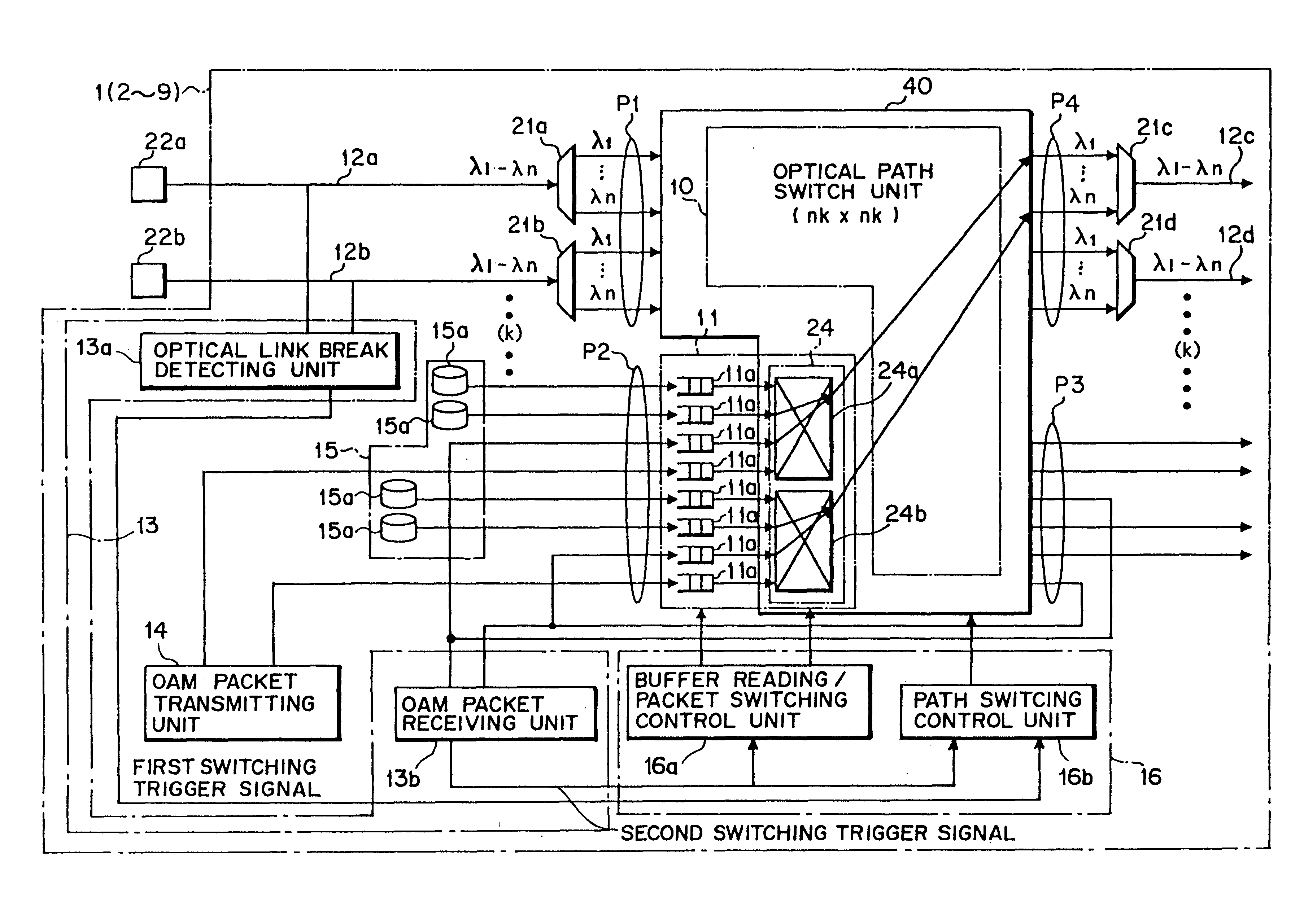
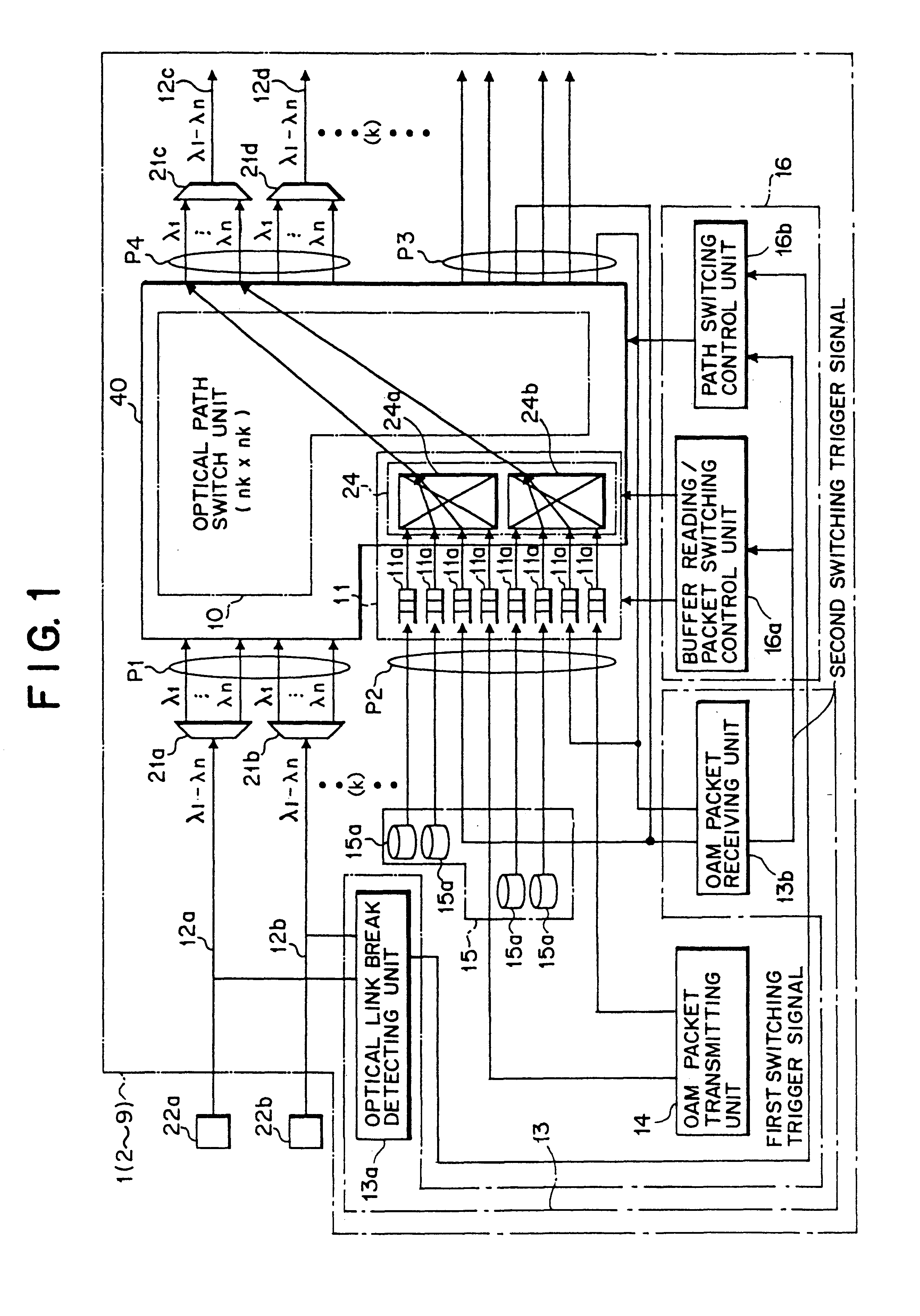
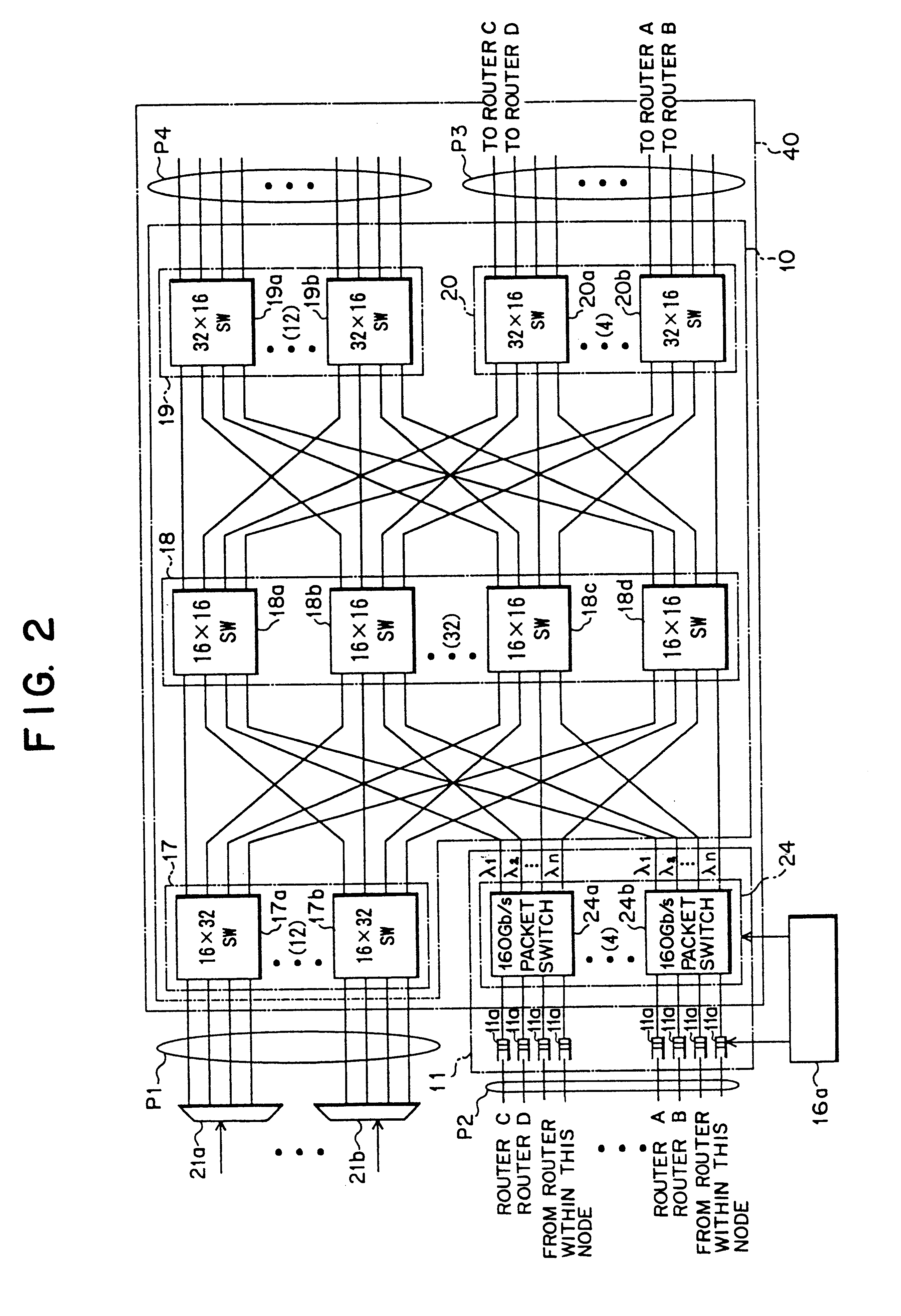
FIG. 2 is a diagram showing an arrangement of the space switch unit 40 according to the present invention. The space switch unit 40 shown in FIG. 2 includes a first input port P1 at which a wavelength division multiplexing optical signal composed of optical signals of a plurality of wavelengths is received, a second input port P2 at which an add-packet with another node address is received, a first output port P3 from which an optical signal with the own node destination extracted from the wavelength division multiplexing optical signal is generated as an optical signal to be dropped, and a second output port P4 from which an optical signal with another node destination contained in the wavelength division multiplexing optical signal and an optical signal containing an add-packet with another node address multiplexed with each other is generated. Further, the space switch unit 40 includes a first packet switch 24, a first space switch 17, a second space switch 18, a third space swit...

second embodiment

(B) Description of the Present Invention

While the optical path network 50 introduced for describing the first embodiment of the present invention is a ring-like one, the present invention is applicable even if the optical path network 50 is arranged as a mesh-like form.

FIG. 13 is a diagram for explaining how IP packets are transferred in the optical path network arranged as a mesh-like form according to the second embodiment of the present invention when no trouble is brought about in the network. As shown in FIG. 13, an optical path network 52 is composed of photonic IP nodes 1 to 9 which are connected so as to form a mesh-like network. In the network, optical signals deriving from wavelength division multiplexing can be transmitted in a bidirectional fashion. Further, the photonic IP nodes 1 to 9 are connected to one another so that a bidirectional optical path is established among the nodes. Thus, routing is effected for IP packets.

The photonic IP nodes 1 to 8 illustrated in FIG....

third embodiment

(C) Description of the Present Invention

In the description of the first embodiment, it is described how traffic is restored for recovering link failure which is brought about in a ring-like optical path network. In the description of the second embodiment, description is made on a case in which traffic is restored by effecting optical path switching and IP packet switching by a source node so that link failure brought about in a mesh-like network is recovered. Further, in the description of the first modification of the second embodiment, description is made on a case in which the path switching or the IP packet switching is effected by the source side node of the photonic IP nodes neighboring the failed link.

In the following description of an embodiment, description will be made on a case where a path is settled by using an identical wavelength in a section in which an optical path for traffic restoration is settled and a case where a path is settled by using a wavelength which is ...


PUM


Abstract

The present invention relates to a technology of an IP node for transferring IP packets accommodated in a wavelength division multiplexing optical signal. The optical IP node of the present invention includes a space switch unit supplied with a wavelength division multiplexing optical signal and a packet with another node destination and generating an optical signal with the self node destination and multiplexing the optical signal with another node destination and an optical signal caused by the packet together and generating the multiplexed signal, link failure detecting unit connected to an input side and an output side of the space switch unit, detecting link failure and generating a detection signal, an OAM packet transmitting unit for generating a monitoring packet at a predetermined time interval, and a traffic restoration control unit connected to the link failure detecting unit, selecting each optical signal depending on the wavelength in response to reception of the detection signal, switching the optical path and generating the optical signal. Each of the optical IP nodes carries out optical path switching on the wavelength division multiplexing optical signal and assignment of an IP packet to be transmitted to an optical signal and switching of the assignment. Thus, the number of optical wavelengths utilized for transmission can be reduced and the size of the optical IP node can be made small.

Description

(1) Field of the InventionThe present invention relates to a photonic node, photonic nodes for transmission and reception, and a method of restoring traffic upon occurrence of link failure in optical path network, which are suitable for use in a technology for accommodating an IP packet in a wavelength division multiplexing optical signal and subjecting to a cross-connection for carrying out routing.(2) Description of Related ArtRecently, owing to a rapid deployment of the internet, the size of traffic running through the transmission network using an IP (Internet Protocol) is progressively increased. For this reason, a technology of IP over WDM (Wavelength Division Multiplexing) system using the wavelength division multiplexing scheme comes to be introduced as a technology for effectively processing the traffic which requires an exchanger having a great amount of exchanging capability.The IP over WDM system is a system for subjecting a packet to a cross-connection operation to carr...

Claims


Application Information

Patent Timeline
IPC IPC(8): H04Q11/00H04J14/02H04B10/032H04B10/27H04B10/077H04B10/079H04B10/291H04B17/00H04J14/00H04L12/28H04L12/42H04L12/437H04L12/70H04L12/931H04Q3/52
CPCH04J14/0227H04Q11/0005H04J14/0241H04J14/0283H04J14/0284H04J14/0293H04Q11/0066H04Q11/0071H04Q2011/0073H04Q2011/0081
Inventor NISHI, TETSUYAKUROYANAGI, SATOSHI
Owner FUJITSU LTD
Why Eureka
Try Eureka