
Low latency data encoder

a data encoder and low-latency technology, applied in the field of audio signal processing, can solve the problems of trade-off between quality degradation and latency reduction, pseudo error detection or concealment of information, etc., and achieve the effect of optimizing the reduction of codeword-position-caused latency and reducing codeword-position-caused latency

Inactive Publication Date: 2004-04-20
DOLBY LAB LICENSING CORP
View PDF6 Cites 13 Cited by
  • Summary
  • Abstract
  • Description
  • Claims
  • Application Information

AI Technical Summary

Benefits of technology

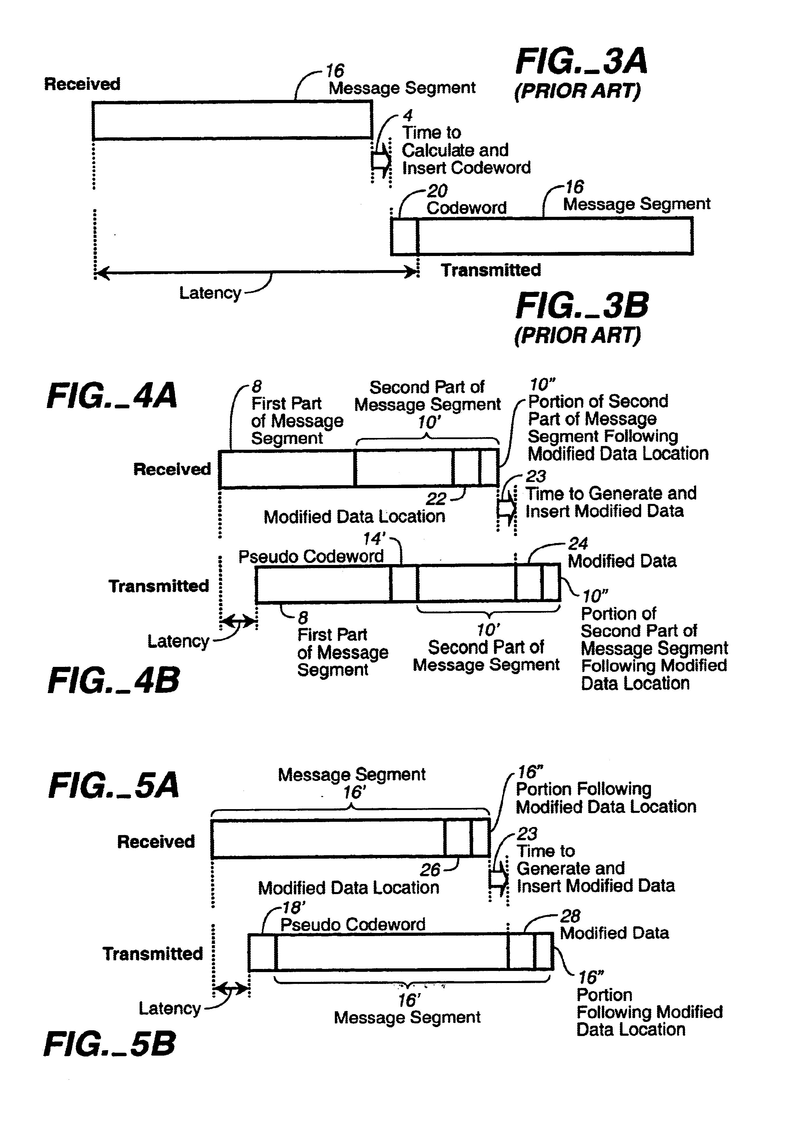
The present invention seeks to reduce codeword-position-caused latency by avoiding the requirement for knowledge of the message prior to generating the error detecting or concealing codeword. A pseudo error detecting or concealing codeword is inserted in place of the normal error detecting or concealing codeword appropriate for the segment of information to which the error detecting or concealing codeword relates. However, in order to satisfy a conventional decoder or receiver, the pseudo error detecting or concealing information must match or be appropriate for the segment so that the decoder sees the codeword and message segment as valid or error free. This is accomplished by modifying or perturbing at least a portion of the segment to which the pseudo codeword relates. Such modification or perturbation may be accomplished in various ways depending on the nature of the error detecting or concealing information. When its nature permits, the segment preferably remains unchanged except in a portion or portions at or near the end of the segment in order to optimize the reduction of the codeword-position-caused latency. The pseudo error detecting or concealing information may be arbitrary (for example, it may be a random number or a pseudo-random number) or, optionally, it may convey information. In either case, the same information may be used as pseudo error detecting or concealing information in connection with all or selected segments, or, alternatively, the information constituting the pseudo error detecting or concealing information may change from segment to segment.
Thus, in one aspect, the invention contemplates a method for reducing latency in the transmission of coded information relative to received information, wherein the coded information includes at least an encoded version of the received information or a modified form of an encoded version of the received information along with error detecting or concealing information appropriate for the coded information. The coded information optionally includes auxiliary information that may include null bits. The coded information is transmitted in a format in which the error detecting or concealing information has an assigned position that does not follow all of the received information or modified form of the received information. Pseudo error detecting or concealing information is generated. The coded information with the pseudo error detecting or concealing information located in the assigned position or positions is generated in which an encoded version of the received information is modified and / or auxiliary information is modified and inserted so that the pseudo error detecting or concealing information is appropriate for the coded information. The coded information is transmitted, whereby the transmission of coded information may begin before all of the received information is received. The pseudo error detecting or concealing information may be in the form of at least one error correcting or concealing codeword. The codeword may be in the form of at least one error detecting cyclic redundancy check (CRC) word.

Problems solved by technology

Nevertheless, in some cases, there may be a tradeoff between quality degradation and latency reduction.
Pseudo error detecting or concealing information is generated.

Method used


Image

  • Low latency data encoder
  • Low latency data encoder
  • Low latency data encoder

Examples


Embodiment Construction

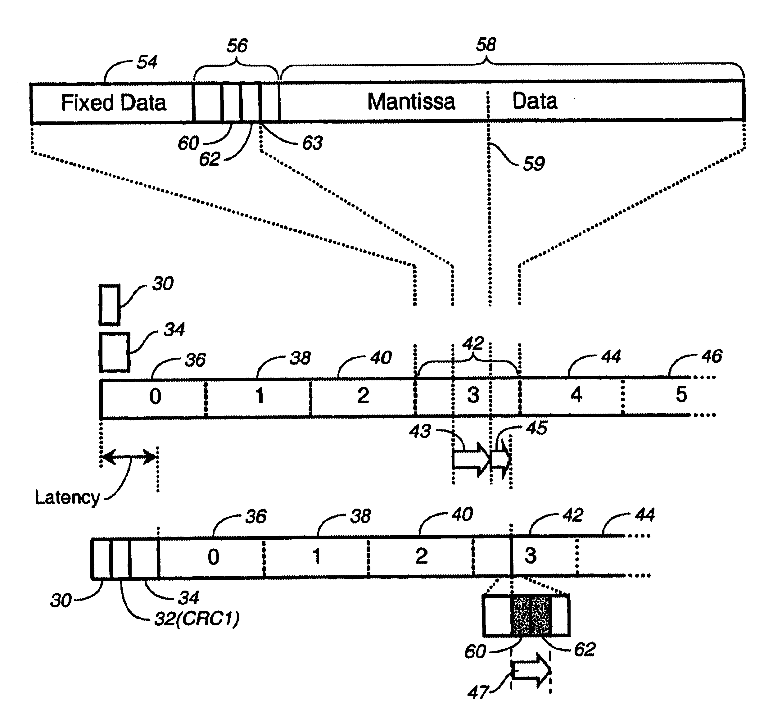
Dolby Digital, a type of perceptual digital audio coding, creates a serial coded audio bit stream made up of a sequence of frames. FIG. 6A shows generally the format of a Dolby Digital frame and, with respect to FIG. 6B, illustrates the latency problem. Each transmitted Dolby Digital frame (FIG. 6B) is assembled from six coded audio blocks 0 through 5 (36, 38, 40, 42, 44, and 46), each of which represents 256 audio samples. A 16-bit sync word 30 sent at the beginning of each frame contains information needed to acquire and maintain synchronization. Each transmitted frame (FIG. 6B) contains two 16-bit cyclic redundancy check words, CRC1 (32) and CRC2 (not shown). CRC1 (32) is the second 16-bit word of the frame, immediately following the sync word 30. CRC2 (50) is the last (50)-bit word of the frame. CRC1 applies to the first 5 / 8ths of the frame, not including the sync word. CRC1 is reverse generated. Latency problems arise with respect to CRC1, as explained below. CRC2 applies to th...


PUM

PropertyMeasurementUnit
time delayaaaaaaaaaa
timeaaaaaaaaaa
transmissionaaaaaaaaaa

Abstract

Codeword-position-caused encoder latency is reduced by avoiding the requirement for knowledge of the message prior to generating an error detecting or concealing codeword associated with the message. A pseudo error detecting or concealing codeword is inserted in place of the normal error detecting or concealing codeword appropriate for the segment of information to which the error detecting or concealing codeword relates. In order to satisfy the requirement of conventional decoders, the pseudo error detecting or concealing information must match or be appropriate for the segment so that the decoder sees the codeword and message segment as valid or error free. This is accomplished by modifying or perturbing at least a portion of the segment to which the pseudo codeword relates. The invention is particularly useful for maintaining the backward compatibility of audio data encoding formats in which the minimum latency is too long (e.g., computer games, where the player performs some operation leading to a sound, and that sound must not be perceptibly delayed with respect to the operation).

Description

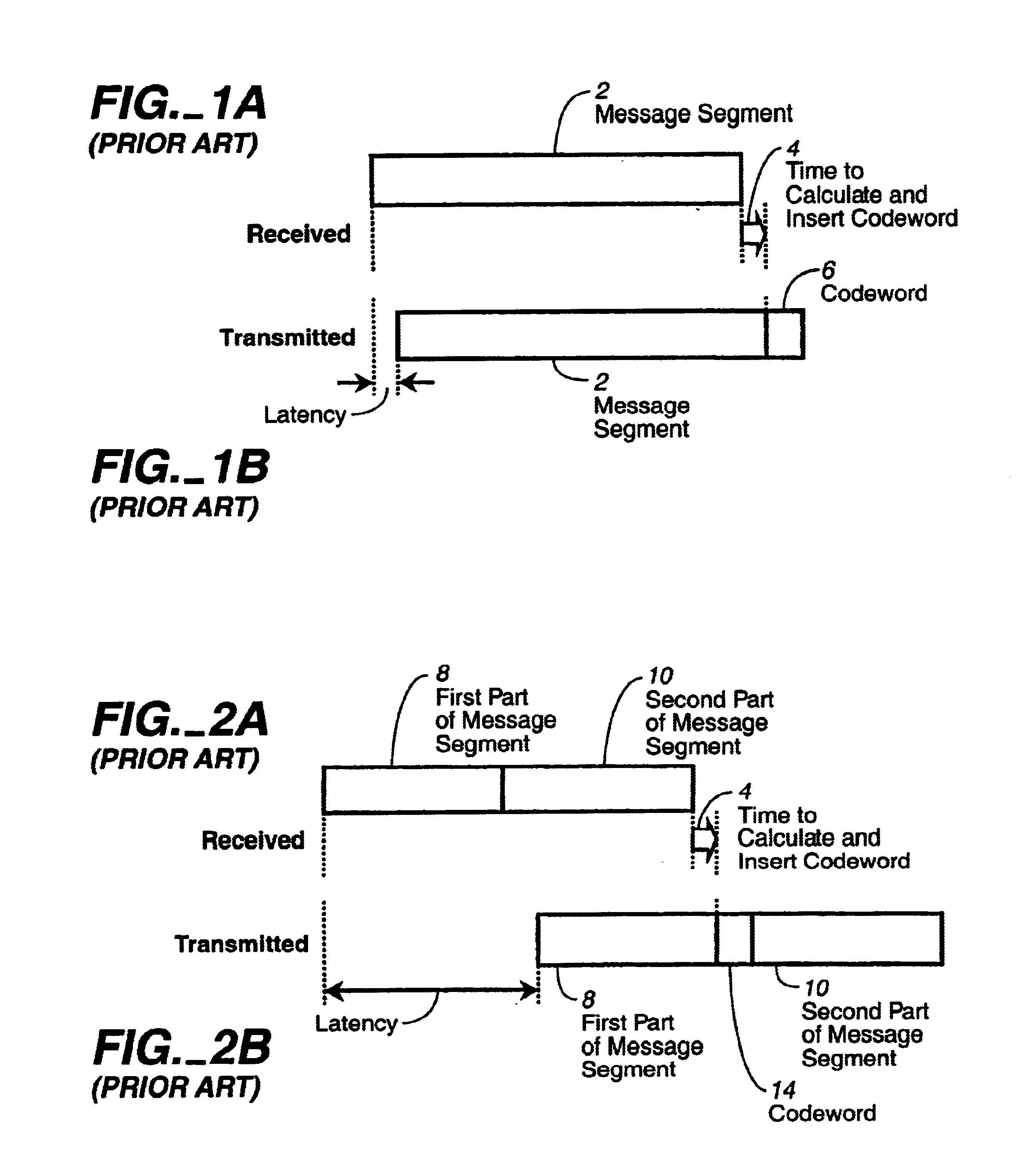
FIELD OF THE INVENTIONThe invention relates to audio signal processing. In particular, the invention relates to the reduction of latency (i.e., time delay) in the digital encoding of audio information.BACKGROUND OF THE INVENTIONVarious methods of data transmission and storage require mechanisms to detect (or detect and conceal) errors. In order to do so, data is often partitioned into portions, packets, or segments such that for a given segment, appropriate error detection or concealment information is generated. This information, typically a codeword or parity word, may be associated with the segment in a known position by an encoding or transmission process. A decoding or receiving system uses the codeword and its associated segment at least to detect the presence of errors, and, possibly to conceal errors. In the prior art, generation of the codeword requires prior knowledge of the entire segment. Consequently, the latency, that is, the time delay, between the receipt of informat...

Claims


Application Information

Patent Timeline
Patent Type & Authority Patents(United States)
IPC IPC(8): H03M13/09H03M13/00G11B20/18G10L19/005
CPCH03M13/09G11B20/1803G10L19/005
Inventor SMITHERS, MICHAEL J.TRUMAN, MICHAEL M.VERNON, STEPHEN D.GUNDRY, KENNETH J.
Owner DOLBY LAB LICENSING CORP
Learn More