

Lithium ion secondary battery
a secondary battery and lithium ion technology, applied in the field of lithium ion secondary batteries, can solve the problems of general design of safety value that cannot be easily operated, and achieve the effects of large battery capacity, increased resistance, and compact and safe design
- Summary
- Abstract
- Description
- Claims
- Application Information
AI Technical Summary
Benefits of technology
Problems solved by technology
Method used
Image

Examples
example 2
Preparation of Positive Electrode
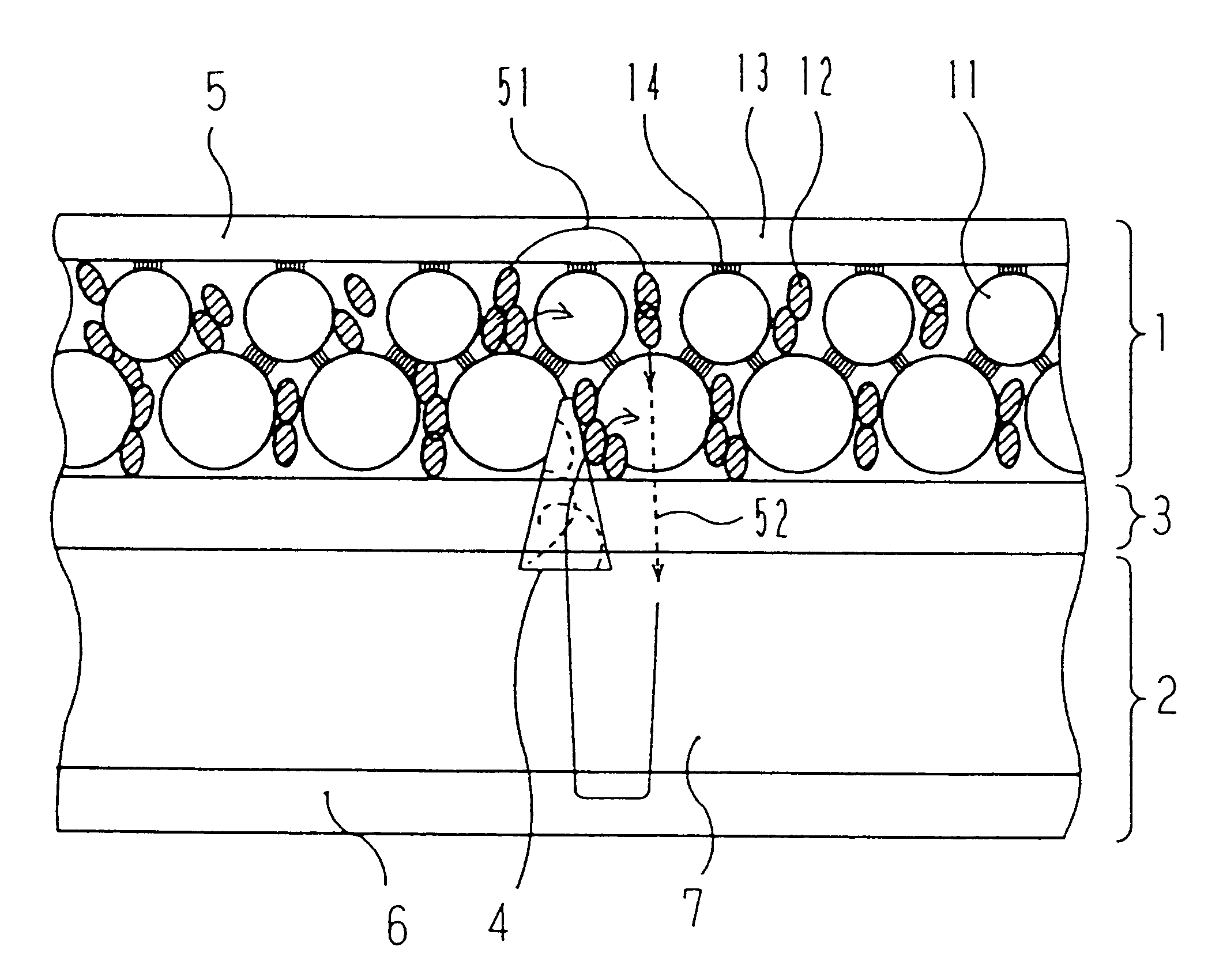
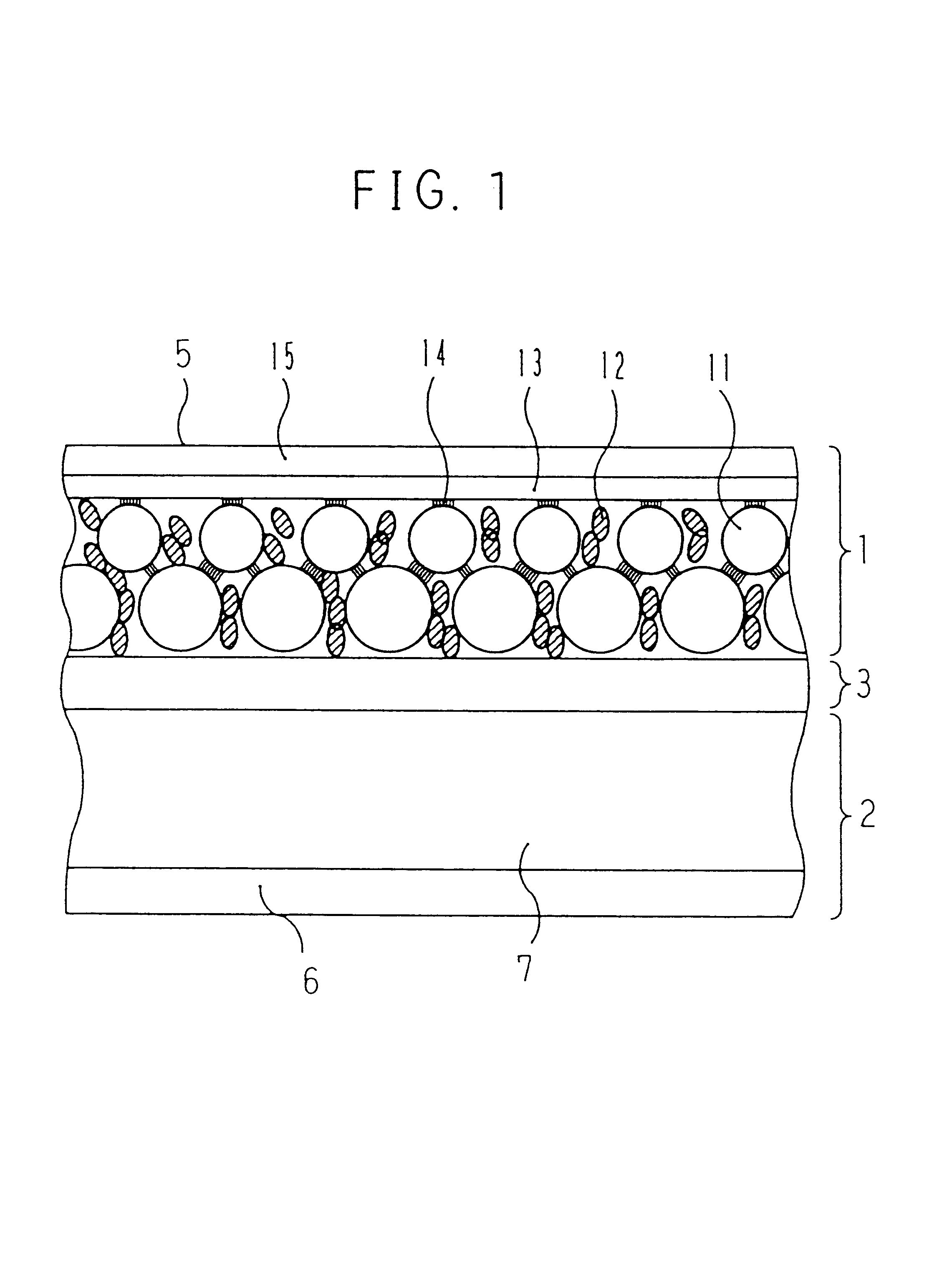
A positive electrode active material paste was prepared by dispersing 85 parts by weight of active material particles having an average particle size of 50 .mu.m made by entangling high density polyethylene having a softening temperature of 120.degree. C. with LiCoO.sub.2 having an average particle size of 1 .mu.m, 10 parts by weight of artificial graphite KS-6 (manufactured by LONZA) as electronic conductive material particles, and 5 parts by weight of PVDF as a binder into NMP. The positive electrode active material paste was applied as thick as 150 .mu.m by a doctor blade process on an aluminum foil having 20 .mu.m thickness forming the positive electrode current collector 5 to form a positive electrode active material film. After being dried at 80.degree. C., the film was pressed to prepare the positive electrode 1 having a 100 .mu.m thickness positive electrode active material layer 11.
Preparation of Negative Electrode
A negative electrode active...
example 3
Preparation of Positive Electrode
A positive electrode active material paste was prepared by dispersing 85 parts by weight of active material particles consisting of LiCoO.sub.2 having an average particle size of 1 .mu.m, 10 parts by weight of artificial graphite KS-6 (manufactured by LONZA) as electronic conductive material particles, and 5 parts by weight of PVDF as a binder into NMP. Then, a mask having 5 mm.times.5 mm slits at an open area ratio of 70% was applied on the positive electrode current collector 5 comprising a 20 .mu.m thickness aluminum net and a sheet-like conductive polymer (thickness 50 .mu.m), which has the PTC properties, conductivity of 5 S / cm at a room temperature and of 5 .mu.S / cm at an operation temperature of 120.degree. C. which was laminated onto the aluminum net. The positive electrode active material paste was applied as thick as 150 .mu.m by a doctor blade process over the mask, to form a positive electrode active material film divided into a plurality...
example 4
Preparation of Positive Electrode
A positive electrode active material paste was prepared by dispersing 85 parts by weight of active material particles comprising LiCoO.sub.2 having an average particle size of 1 .mu.m, 10 parts by weight of artificial graphite KS-6 (manufactured by LONZA) as electronic conductive material particles, and 5 parts by weight of PVDF as a binder into NMP. Then, the positive electrode active material paste was applied as thick as 150 .mu.m by a doctor blade process on the positive electrode current collector 5 forming a 20 .mu.m-thick aluminum net to form a positive electrode active material film. After being dried at 80.degree. C., the film was pressed to prepare the positive electrode 1 having a 100 .mu.m thickness positive electrode active material layer 11.
Preparation of Negative Electrode
A negative electrode active material paste prepared by dispersing 95 parts by weight of particles having an average particle size of 50 .mu.m obtained by entangling h...
PUM
| Property | Measurement | Unit |
|---|---|---|
| softening temperature | aaaaa | aaaaa |
| temperature | aaaaa | aaaaa |
| temperature | aaaaa | aaaaa |
Abstract
Description
Claims
Application Information