Linear motion guide unit with joint tube between return passage and turnaround

a technology of motion guide unit and return passage, which is applied in the direction of bearings, bearings, shafts and bearings, etc., can solve the problems of difficult replacement with new ones, limited amount of lubricant used, and unfit machines, etc., and achieves inexpensive lubrication and reduces sliding resistance

Inactive Publication Date: 2004-05-04
NIPPON THOMPSON
View PDF14 Cites 19 Cited by
  • Summary
  • Abstract
  • Description
  • Claims
  • Application Information

AI Technical Summary

Benefits of technology

The present invention has for its primary object to overcome the challenge as described just above, especially provide a linear motion guide unit in which a sleeve of sintered resinous material capable of impregnated with lubricant fits in a through-hole bored in a carriage to form a return passage, and a joint tube is applied at a junction of a turnaround in an end cap with any one of forward and aft ends of the sleeve to make sure of smooth rolling of the rolling elements at the junction. The present invention provides a linear motion guide unit made free from maintenance such as periodic application of lubricant and / or suppliance of lubricating oil to the rolling elements running through the recirculating circuit made up of a load raceway, turnarounds and a return passage, even under the severe operating conditions in atmosphere and / or subjected load. The present invention also provides a linear motion guide unit in which the joint tube applied at a junction of the turnaround with the return passage contributes to reducing the sliding resistance that might be encountered when the rolling elements run through the recirculating circuit used in the high-speed, high-cycle machines, thereby realizing inexpensive lubrication.
With the linear motion guide unit of the present invention, especially, the carriage is made of metal whereas the sleeve for return passage discussed here is made of sintered resinous material relatively fragile compared with metal. Nevertheless, the sleeve is held in the through-hole with zero fit in which there is no clearance between the sleeve and the through-hole in the metal carriage and / or with clearance fit, that is, with any clearance fit having any positive or zero allowance, instead of force fit in which interference always results on assembly of the sleeve in the through-hole. Thus, there is no occurrence of breakage such as cracks in the sleeve for return passage. Moreover, the clearance fit on assembly of the sleeve in the carriage contributes to no possibility of the occurrence of any breakage in the sleeve, which might result from the difference in thermal expansion between the carriage and the sleeve, thus making ensure high durability of the sleeve for return passage.
With the linear motion guide unit constructed as stated earlier, the joint tube made up of the outside part on the end cap and the outside part on the spacer is effective to make certain of extremely steady junction of the return passage with the turnaround, and connect between the return passage and the turnaround with precision and smoothness to thereby reduce the sliding resistance that is encountered when the rolling elements run over the junction, helping the rolling elements roll smoothly. That is to say, according to the linear motion guide unit of the present invention, the joint tubes are arranged to make end-to-end abutment against the forward and aft edge of the sleeve to complete the return passage, and in doing so establish the smooth passage in the whole time of recirculation, thus making sure the rolling elements smoothly run through the overall recirculating circuit.
The sleeve for return passage is made of sintered resinous material of porous structure taking on the function of an absorber readily soaking up lubricating oil or grease. Thus, the sleeve soaked with the lubricating oil or grease can perform proper lubrication of the rolling elements. That is to say, the lubricating oil or grease absorbed and reserved in the porous structure is transferred little by little to the rolling elements when making contact with the rolling elements. The lubricant adhered on the rolling elements is then applied to the load raceways as the rolling elements run through the load raceways. The sleeve for return passage made of sintered resinous material has sufficient strength in itself and on itself even with no other reinforcement. Moreover, the sintered resinous material used in the present invention, as being less subjected to wear, is tough to clogging in the porous structure, which might be caused by cuttings, debris, and so on occurring due to wear, thereby to make it possible to continue supplying over a prolonged period the rolling elements with lubricant, which is reserved in the porous structure.
Moreover, the sleeve made of sintered resinous material is flanked by the joint tubes at the forward and aft ends thereof. This construction can keep the sintered resinous material of the sleeve away from the threat that the balls might batter away on the sleeve at the entrance to the return passage, helping the sleeve of sintered resinous material survive for a long period.
Consequently the linear motion guide unit of the present invention is made free from maintenance such as periodic application and / or suppliance of lubricant over the prolonged period. Until the lubricant is consumed transferred from the return passage to the rolling elements, there is no need to replenish the return passage with lubricant. Moreover, the linear motion guide unit of the present invention lessens the sliding resistance at the load raceway to the extent conforming to the high speed and high cycle of the machines.

Problems solved by technology

Moreover, it is inevitable to limit the amount of lubricant used as least as possible since fine mist of lubricant might contaminates the atmosphere in the clean room.
It will be said this construction is unfit for the machines that need maintenance-free operation.
However, since the tube for the return passage is forcibly fit in the through-hole in the carriage, replacement with new one is very tough job.
Although but the prior linear motion guide units recited just above can operate successfully with no application of lubricant so long as used under light loads in the clean room specifications, they do not always serve well for the recently advanced machinery that has become increasingly higher in speed and oscillation.
With the construction in which the lubricating plates were mounted on the slider to make sliding engagement with the track rail, there is the problem that the slider has caused large frictional resistance when it was applied to machinery high in speed and oscillation.
Modern advanced machinery has a tendency to get higher in working speed and oscillation.

Method used


Image

  • Linear motion guide unit with joint tube between return passage and turnaround
  • Linear motion guide unit with joint tube between return passage and turnaround
  • Linear motion guide unit with joint tube between return passage and turnaround

Examples


Embodiment Construction

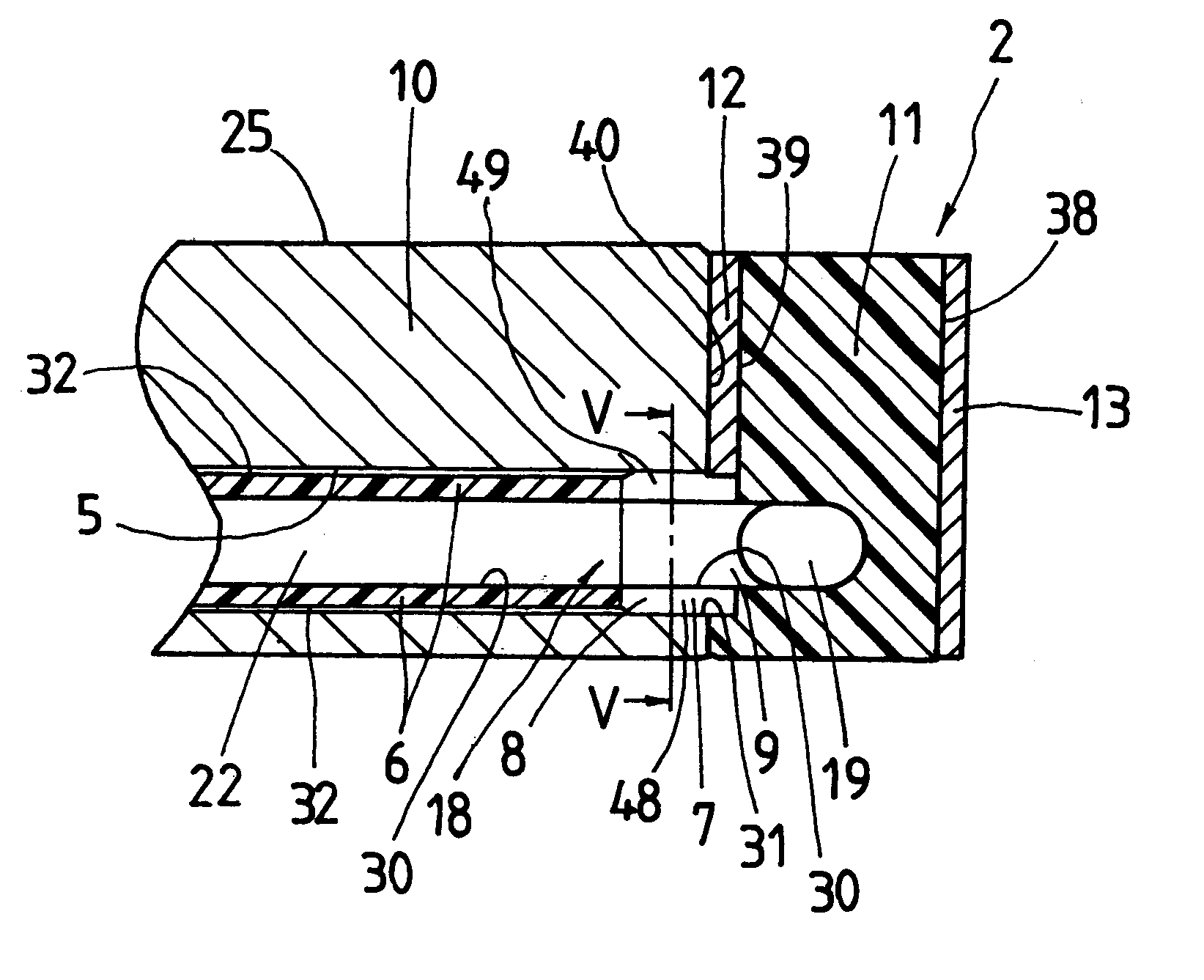
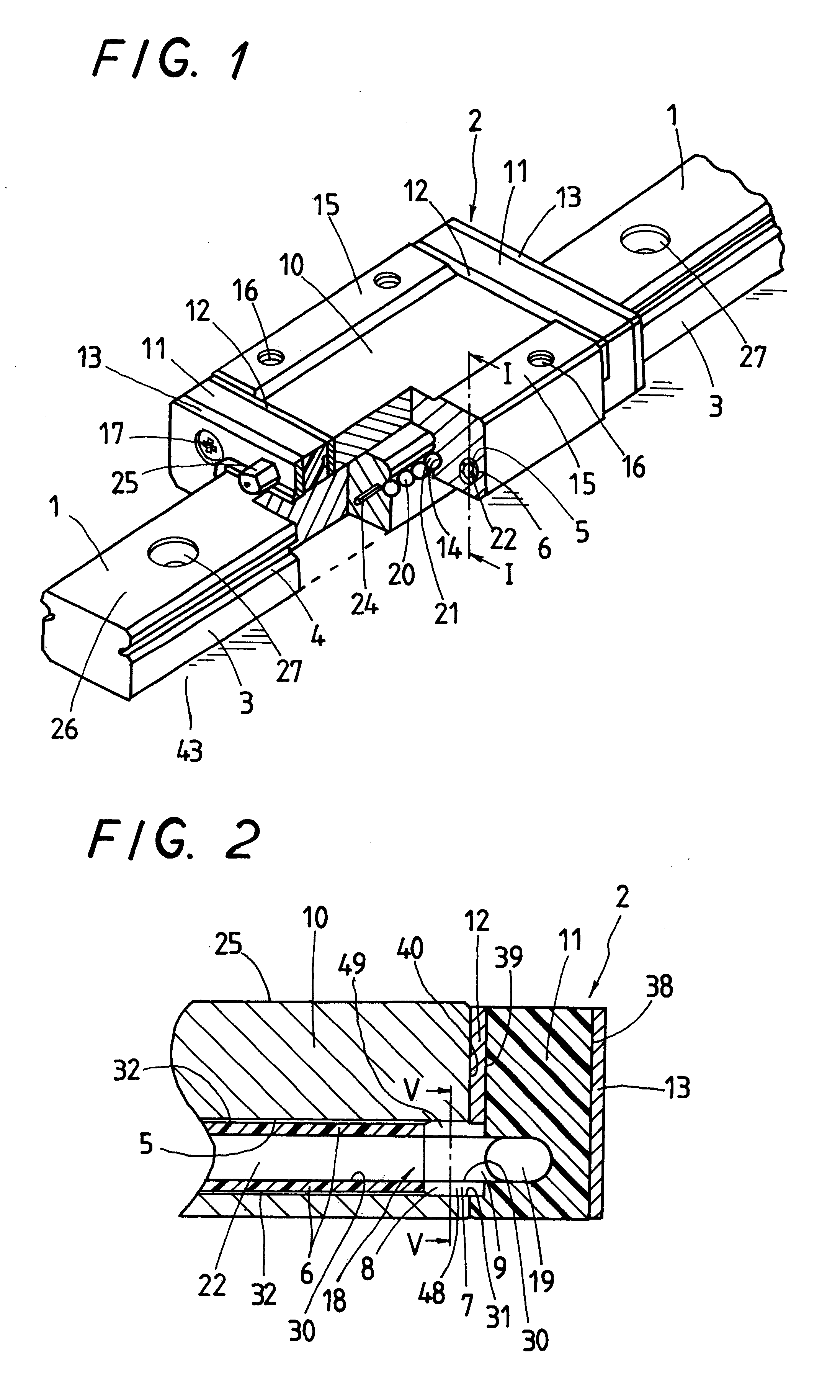
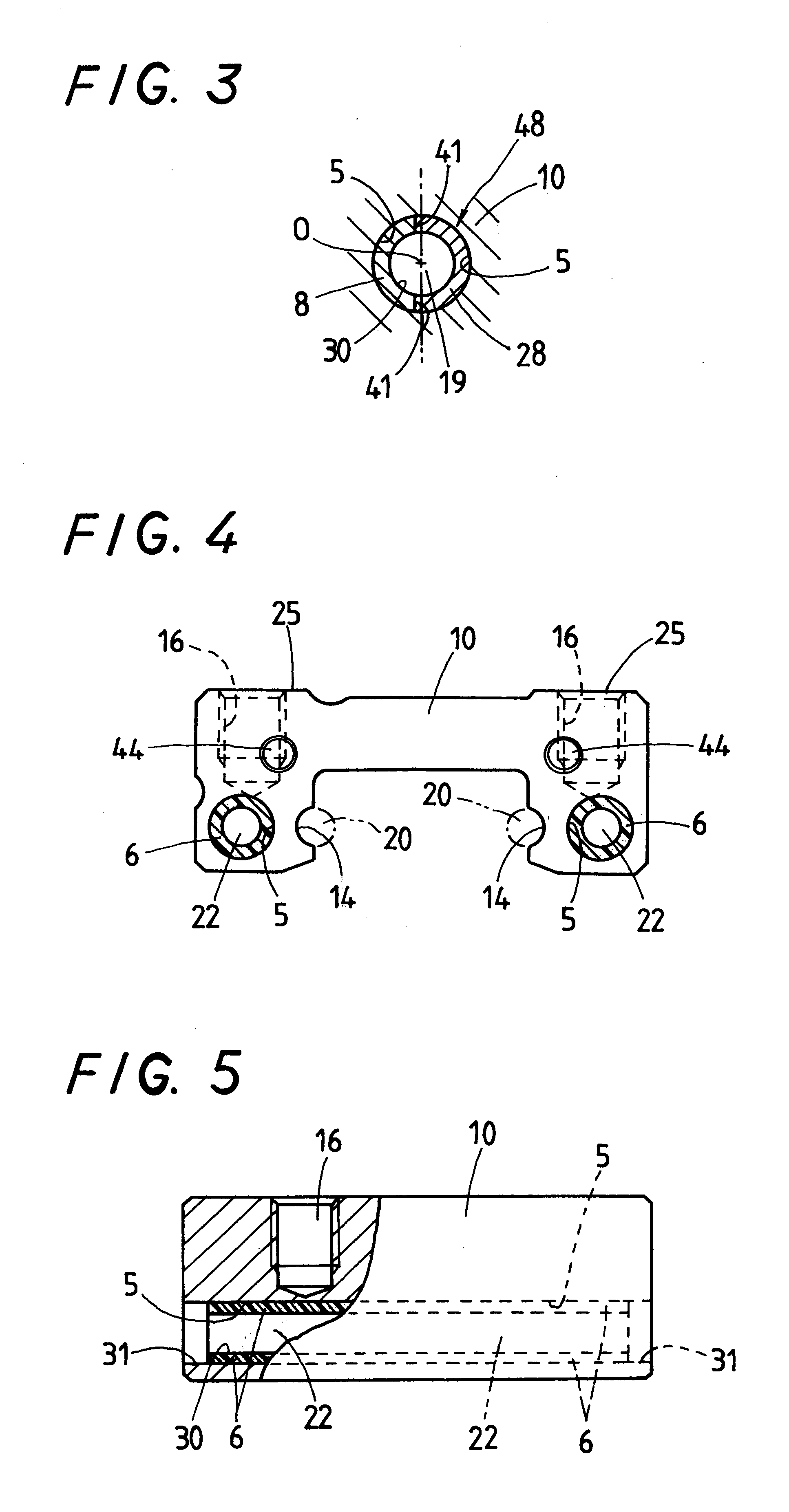
Referring now in detail to the drawings, a linear motion guide unit according to the present invention will be explained below. This linear motion guide unit will be interposed between any confronting parts or components movable relatively to one another in machinery such as semiconductor manufacturing equipments, industrial robots, machine tools, engines, and so on to make sure of smooth relative travel between the confronting parts or components. The linear motion guide unit of the present invention is chiefly marked by a joint tube to connect a turnaround with a return passage.

The linear motion guide unit of the present invention is applicable between any relatively traveling components: machine bed and table confronting each other and movable with respect to one another, and mainly comprised of an elongated track rail 1 having lengthwise-extended raceway grooves 4 (later called first raceway groove) on sides 3 thereof, one raceway groove to each side, and a slider 2 that fits as...


PUM


Abstract

A linear motion guide unit is disclosed in which a joint tube connects between a turnaround and a return passage of a sleeve made of sintered resinous material to ensure smooth turnabout of rolling elements and further in which lubricant can be supplied to the rolling elements for a prolonged period, thereby refining the durability. A slider is comprised of a sleeve for a return passage held with clearance fit in a through-hole of a carriage in a way lining major area of the through-hole with only forward and aft ends of the through-hole being left naked, a spacer with a lug having a radially inside curved half for a turnaround and an inside part for a joint tube to make up for any one end of the return passage joining with the radially inside curved half, and an end cap having a radially outside half for the turnaround and an outside part for the joint tube to make up for any one end of the return passage joining with the radially outside curved half.

Description

BACKGROUND OF THE INVENTION1. Field of the InventionThe present invention relates to a linear motion guide unit envisaged to treat well high speed and high cycle in modern advanced machines such as semiconductor manufacturing equipments, industrial robots, engines, and so on, and more particularly a linear motion guide unit in which sintered resinous material of porous structure is installed in a carriage to provide a return passage therein while a joint tube communicates the return passage with turnarounds formed in the end caps.2. Description of the Prior ArtThe conventional linear motion guide units are commonly so constructed that a slider is movable relatively of an elongated track rail through many rolling elements, which are allowed to run through recirculating circuits comprised of load areas of raceways defined between the track rail and the slider, and non-loaded areas including turnarounds in end caps and return passages in a carriage in the slider. To help prevent metal-...

Claims


Application Information

Patent Timeline
Patent Type & Authority Patents(United States)
IPC IPC(8): F16C29/06F16C33/66
CPCF16C29/0609F16C29/0611F16C29/064F16C33/6611F16C33/6622F16C33/6648
Inventor MATSUI, TAKESHIITABASHI, SHIGEMASAISHIHARA, TOYOHISA
Owner NIPPON THOMPSON
Why Eureka
Try Eureka