Telecommunications system
a technology of telecommunications system and remote terminal, applied in the field of optical communication system, can solve the problems of increasing the cost, complexity and electrical increasing the cost and power consumption of the terminal equipment used to supply signals, and increasing the cost and complexity of the remote terminal
- Summary
- Abstract
- Description
- Claims
- Application Information
AI Technical Summary
Benefits of technology
Problems solved by technology
Method used
Image
Examples
example
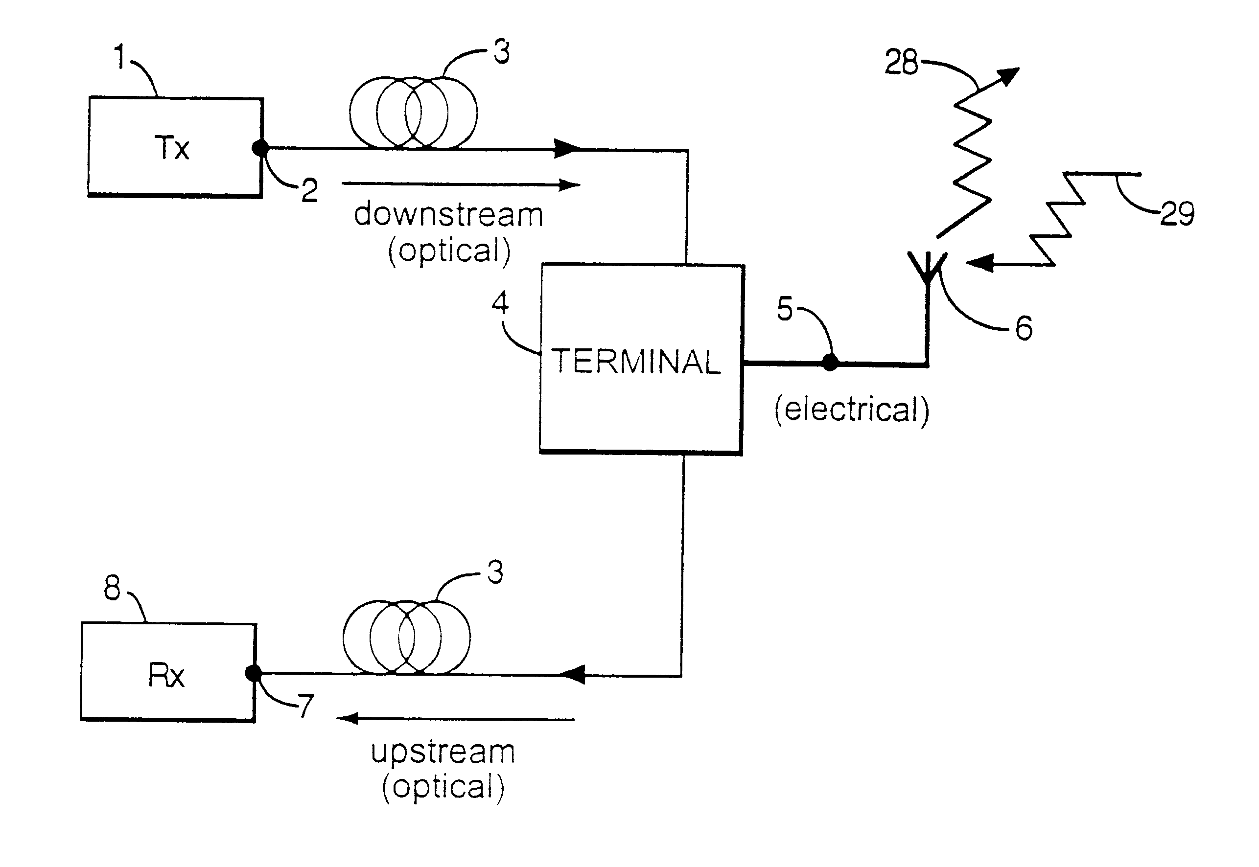
An erbium-doped optical fibre amplifier was used at the head end to boost the launched optical signal level on the downlink to 15 mW. With this power level an experiment was conducted on outdoor propagation. The same antennas and remote terminal were used. The results are shown in FIG. 18. As can be seen, the furthest separation used was 75 meters, at which the power level at the remote terminal was -78 dBm.
Higher Antenna Gain at the Electro-Absorption Modulator
Here the question is how does one want to trade directionality for gain. Obviously it is possible to use a highly directional antenna, for example antennas with gains of 18 dB are available, but they are typically very bulky and have very narrow beam widths. In experiments to date we have used an antenna which is no larger than a packet of cigarettes, which has an 8 dB gain and a 70.degree. beam width. One could, at the price of extreme directionality, get a 10 dB increase in signal-to-noise ratio, that is a range increase fa...
example 2
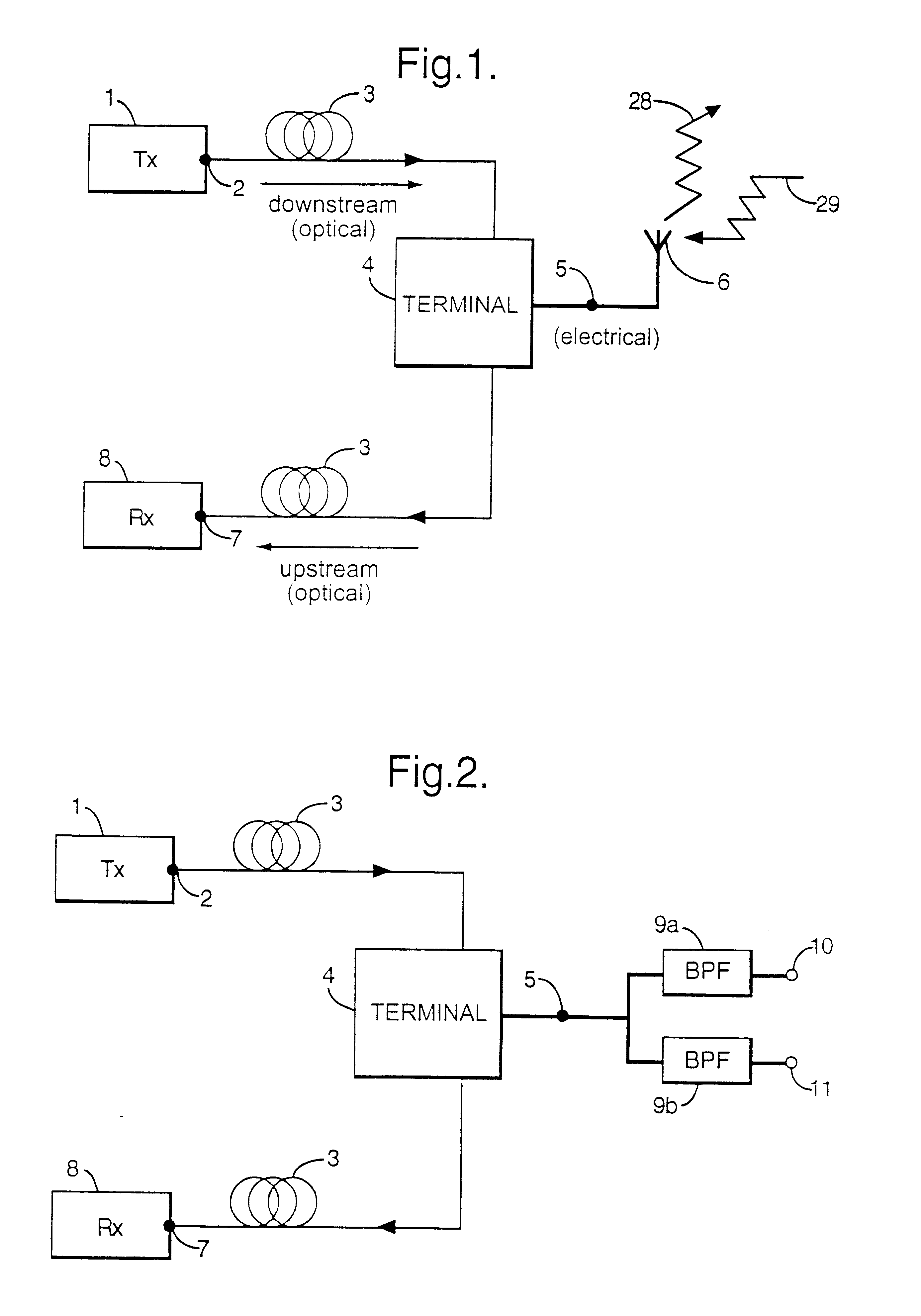
The experimental optical configuration is shown in FIG. 8. A single, low insertion-loss, EA modulator module is used at the remote terminal. A practical low cost / low power system would most likely use EA modulators at each terminal thereby eliminating entirely the need for analogue laser transmitters. FIG. 9 shows two possible network configurations which use only EA modulator transceivers. In FIG. 9a, several point-to-point links share a common CW laser optical (high) power source. In each link, a remote transceiver, EAM#2, is connected to a transmitter, EAM#1, and receiver, EAM#3. In FIG. 9b, a number of EA transceivers share an optical bus powered at the ends by two CW lasers (i.e. all transceivers share the same RF spectrum.).
In our experiment, a 120 MB / s QPSK modem signal, up-converted to 1.347 GHz, is combined with the down-converted TV channels from one polarisation of the Astra (TM) group of satellites. The combined signal is then applied to a commercial analogue DFB laser m...
example 3
In Example 2 we showed how a single electroabsorption modulator (EAM) can be used in a "star" type of network architecture as a low cost device to deliver high data rate channels together with multi-channel FM and digital TV. In this example, we present the use of EA modulators for single fibre, bidirectional optical bus topology operation, delivering 120 Mb / s QPSK channels. The optical bus is powered by two CW lasers, thereby avoiding the use of expensive high speed lasers. Potentially, the cost of the CW laser sources would be shared among users located at the access nodes. Furthermore, since all nodes are connected in series, the bus has to afford a certain degree of resilience. The EAM is an ideal candidate for this application: a power failure at one node (Bbias=0 volt), would leave the EAM to operate in a virtually transparent optical state, therefore leaving the rest of the network in tact.
Experiment: FIG. 13 shows the experimental setup. Two EA modulators (EAM1 and EAM2) wer...
PUM
 Abstract
Description
Claims
Application Information
 - R&D
- Intellectual Property
- Life Sciences
- Materials
- Tech Scout
- Unparalleled Data Quality
- Higher Quality Content
- 60% Fewer Hallucinations
Browse by: Latest US Patents, China's latest patents, Technical Efficacy Thesaurus, Application Domain, Technology Topic, Popular Technical Reports.
© 2025 PatSnap. All rights reserved.Legal|Privacy policy|Modern Slavery Act Transparency Statement|Sitemap|About US| Contact US: help@patsnap.com


