Methods and devices for vascular plethysmography via modulation of source intensity

a plethysmography and source intensity technology, applied in the field of noninvasive and implantable (i. e., invasive) plethysmography methods and devices, can solve the problems of poor volume change measurement, low accuracy, and inability to accurately measure the volume of the plethysmography, so as to achieve the effect of minimizing the differen

Inactive Publication Date: 2004-05-04
PACESETTER INC
View PDF5 Cites 245 Cited by
  • Summary
  • Abstract
  • Description
  • Claims
  • Application Information

AI Technical Summary

Benefits of technology

According to an embodiment of the present invention, the light control signal is adjusted to minimize a difference between the feedback signal and a reference signal. T

Problems solved by technology

Thus, its usefulness is generally limited to pulse-velocity measurements, determination of heart rate, and an indication of the existence of a pulse (e.g., in a finger).
Additionally, a conventional PPG provides a poor measure of changes in volume and is very sensitive to motion artifacts.
This approach is not optimal for many reasons, some of which are discussed above and others of which are discussed below.
First, providing a constant average optical power does not allow for power consumption to be minimized.
However, if the plethysmography device is an implantable device (or part of an implantable device), as is the case in many embodiments of the present invention, the device is likely powered by a

Method used


Image

  • Methods and devices for vascular plethysmography via modulation of source intensity
  • Methods and devices for vascular plethysmography via modulation of source intensity
  • Methods and devices for vascular plethysmography via modulation of source intensity

Examples


Embodiment Construction

The following description is of the best modes presently contemplated for practicing the invention. This description is not to be taken in a limiting sense but is made merely for the purpose of describing the general principles of the invention. The scope of the invention should be ascertained with reference to the claims. In the description of the invention that follows, like numerals or reference designators will be used to refer to like parts or elements throughout.

I. Overview of Present Invention

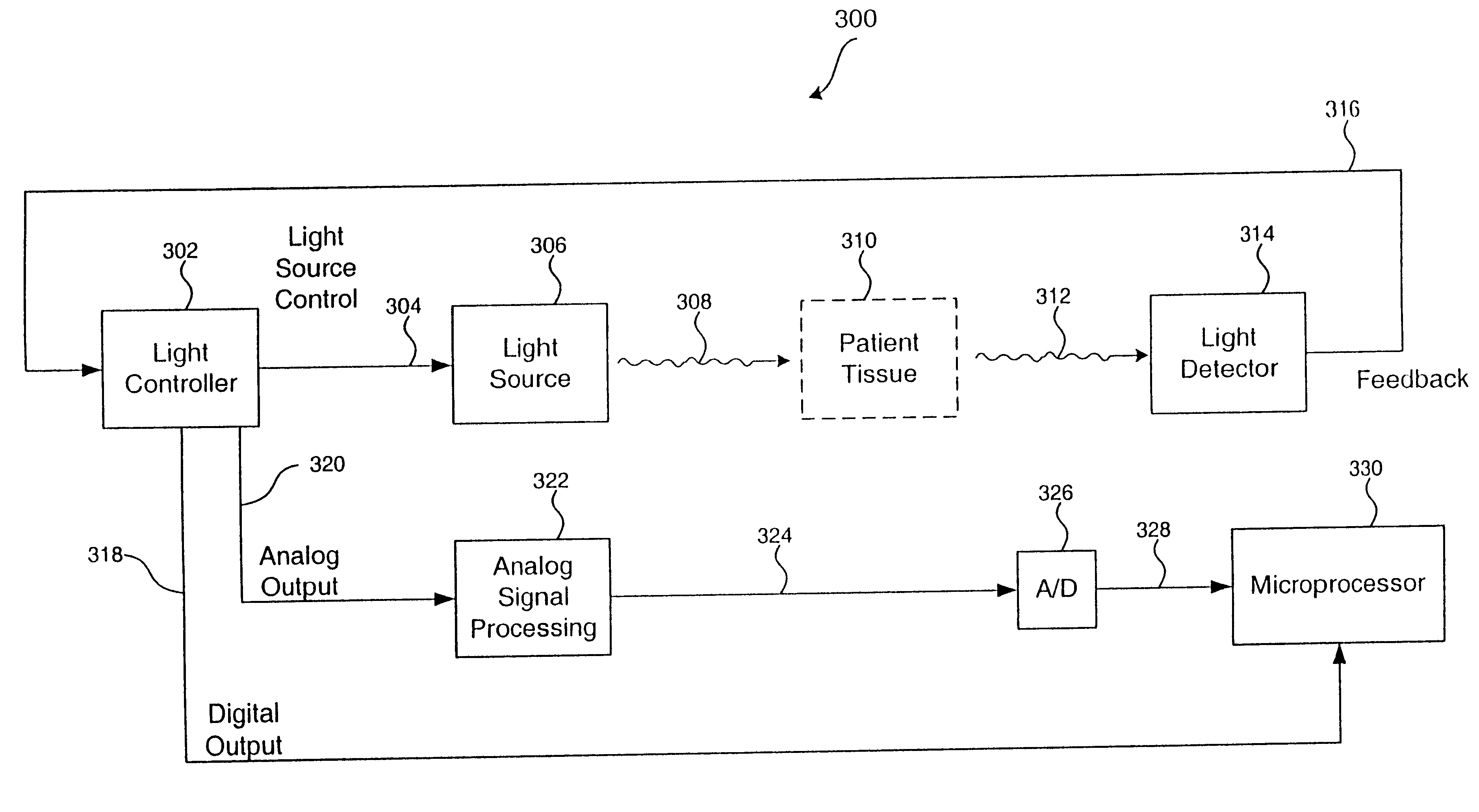
Instead of providing a constant source of optical power (e.g., a light source having a constant intensity) and using a time-varying detected signal as the plethysmography signal (i.e., the information signal), the present invention adjusts the source of optical power such that a relatively constant average light intensity is detected at a light detector. The time-varying modulating signal (i.e., that controls the source power) is used as the plethysmography signal (i.e., the information ...


PUM


Abstract

A time-varying modulating signal is used as a plethysmography signal, rather than a time-varying detected optical power. The time-varying detected optical power is used (e.g., in a feedback loop) to adjust the source intensity. Light is transmitted from a light source, wherein an intensity of the transmitted light is based on a light control signal. A portion of the light transmitted from the light source is received at a light detector, the portion having an associated detected light intensity. A feedback signal is produced based the portion of light received at the light detector, the feedback signal indicative of the detected light intensity. The feedback signal is compared to a reference signal to produce a comparison signal. The light control signal is then adjusted based on the comparison signal, wherein at least one of the comparison signal and the light control signal is representative of volume changes in blood vessels.

Description

BACKGROUND OF THE INVENTION1. Field of the InventionThe present invention relates generally to non-invasive and implantable (i.e., invasive) plethysmography methods and devices. The present invention more particularly relates to methods and devices for monitoring volume changes in a limb or tissue segment of a patient. The present invention also relates to methods and devices that calculate blood oxygenation levels.2. Background ArtPlethysmography is a generic term referring to a variety of techniques for monitoring volume changes, for example, volume changes of the lungs due to respiration, or of blood vessels of a limb or tissue segment. When applied to measurements of blood volume, changes occur in a pulsatile manner with each beat of the heart as blood flows in and out of a portion of the body. The study of vascular activity by fluid displacement methods dates hack to at least 1890. More contemporary techniques include strain gauge, pneumatic, impedance, doppler, and photoelectr...

Claims


Application Information

Patent Timeline
IPC IPC(8): A61B5/026
CPCA61B5/0261
Inventor TURCOTT, ROBERT
Owner PACESETTER INC
Why Eureka
Try Eureka