Programmable emergency-stop circuit with testing

a technology of emergency stop circuit and testing circuit, which is applied in the direction of slip coupling, program control, instruments, etc., can solve the problems of power loss (i.e., shutting off), return of machine to unsafe use, wear and tear of lever switch,

Inactive Publication Date: 2004-05-11
EIGENPOINT
View PDF15 Cites 99 Cited by
  • Summary
  • Abstract
  • Description
  • Claims
  • Application Information

AI Technical Summary

Problems solved by technology

For example, lever-type switches are installed on door panels, so that power is killed (i.e., shut off) when one of the doors opens.
When there are several doors defeated in this manner located throughout a large machine, the probability is higher than desirable for a maintenance technician to inadvertently leave a switch defeated and return the machine to what will be unsafe use.
Also, the cycle of taping/strapping and removal thereof causes wear and tear on the lever-type switch for which it was not designed.
This also creates opportunity for mistakenly leaving kill switches defeated (or misaligned) throughout the machine when it is returned to service.
Afterwards, forgetting to re-enable the switch allows running of the spindle without air, which leads to hardware damage.
Oversight due to distribution of the switches over numerous parts of the machine/device can cause him to forget to re-enable a kill switch before returning equipment back to duty.
There is no straightforward, universal way to do this other than disconnecting the power to the device.
This may be easy in some cases or not possible, very cumbersome, or unsafe in others.
But these are also the reasons why the circuit has not matured.
Also, some kill switches having solid state outputs (e.g. NPN) do not fit into the serially connected topology.
Such functionality, if implemented, is therefore left to be distributed throughout the remainder of the system, interming...

Method used


Image

  • Programmable emergency-stop circuit with testing
  • Programmable emergency-stop circuit with testing
  • Programmable emergency-stop circuit with testing

Examples


Embodiment Construction

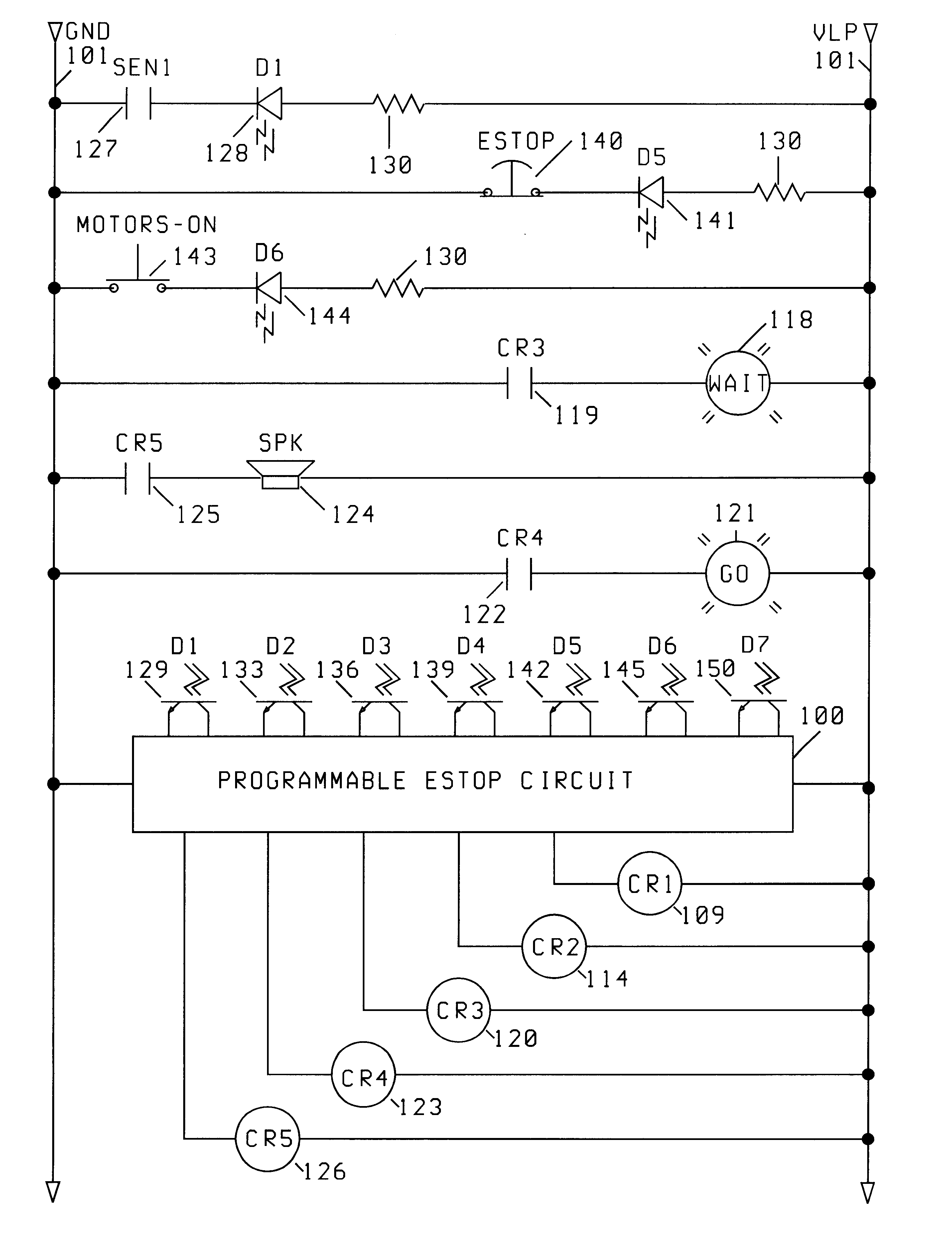
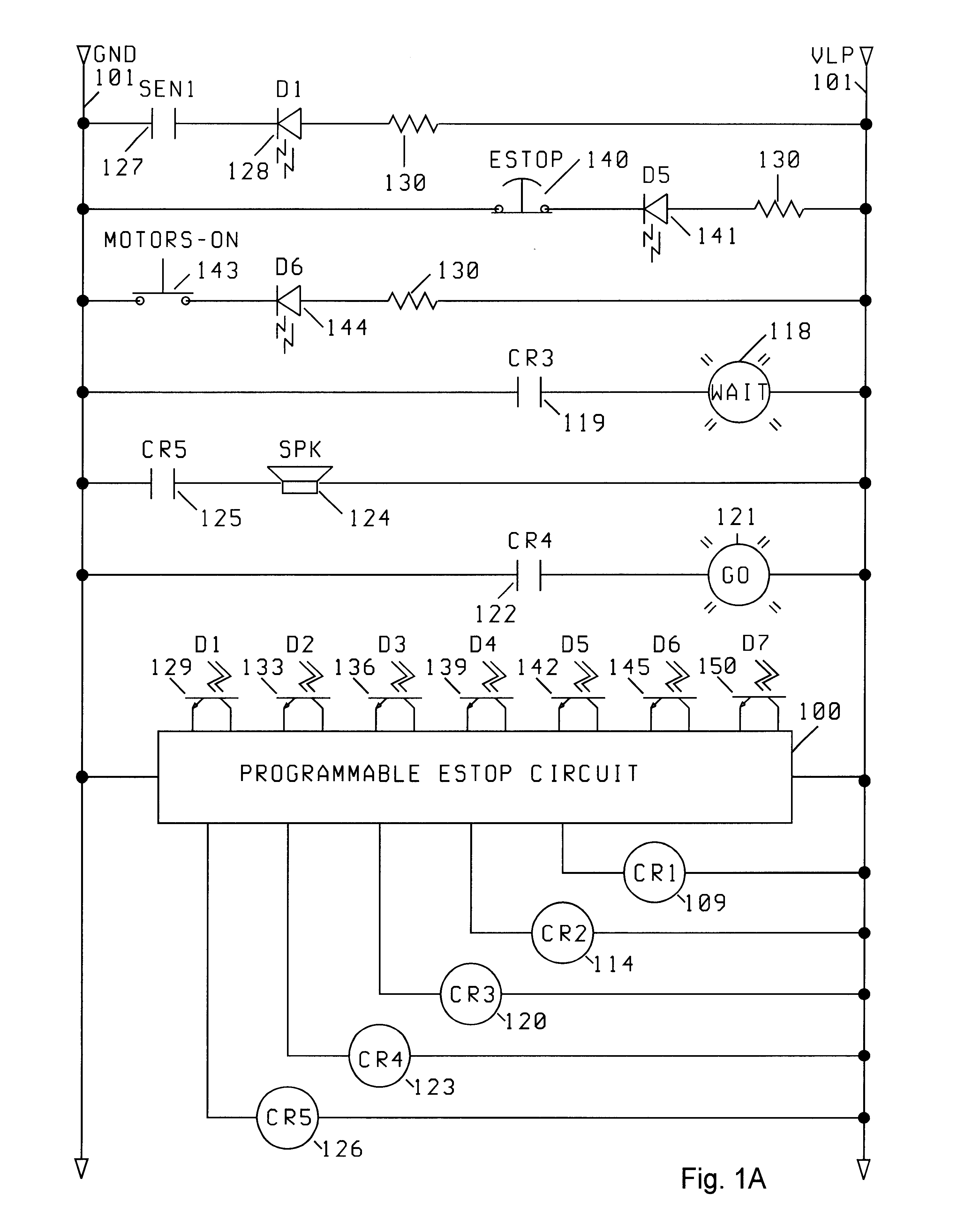
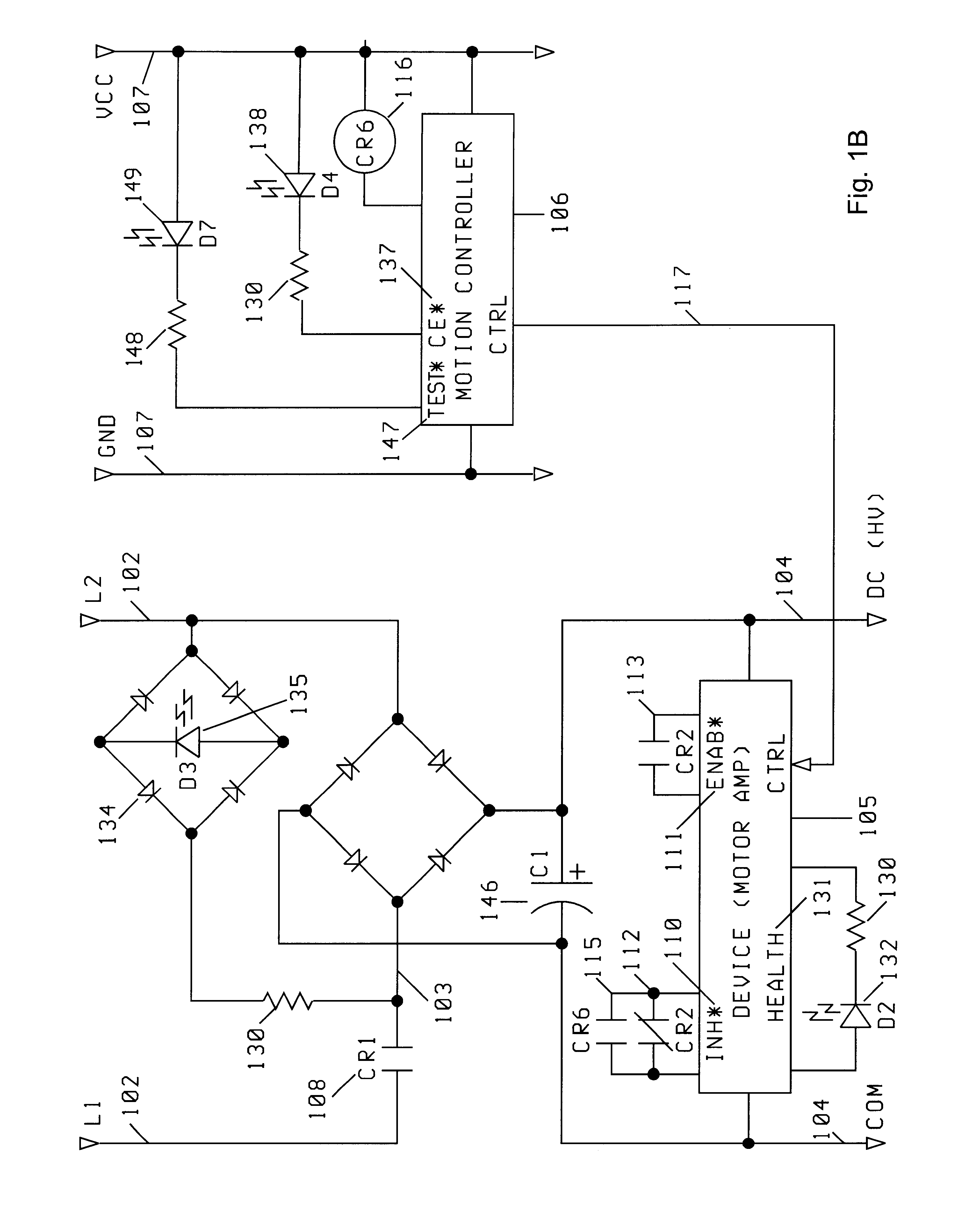
Referring now to the figures in which like numerals represent like elements throughout several views, the present invention comprises a programmable emergency-stop circuit 100 that is programmable on multiple levels and provides advanced functions not found in other systems. The circuit centralizes the control of high voltage motor power into one place, by providing connections for, in its minimum configuration, several different kill switches, a motors-on button, and an AC motor power relay coil. In contrast with the traditional emergency-stop circuit, which has a serially connected architecture, distributed throughout the machine, the present circuit adopts a more centralized topology. Kill switches, emergency-stop and motors-on buttons, computer ready, watchdog, and test signals are all conveniently connected in one location, alongside the AC motor power relay coil driver.

As described in more detail hereinafter, the invention enhances the traditional emergency-stop circuit by (1)...


PUM


Abstract

The invention includes a programmable emergency-stop circuit apparatus and method that provides advanced function not found in other systems. The circuit centralizes the control of high voltage motor power into one place, by providing connections for, in its minimum configuration, several different kill switches, a motors-on button, and an AC motor power relay coil. In the present invention, kill switches, test inputs, emergency-stop and motors-on buttons, computer ready and watchdog signals are all conveniently connected in one location, alongside the AC motor power relay coil driver. Programmable options exist for testing kill inputs online, while the emergency stop is energized.

Description

The present invention relates to an emergency-stop circuit, which is an integral part of the typical industrial machine. More particularly, this invention relates to a centralized switching system and method for an emergency stop circuit.BACKGROUND INFORMATIONIn industrial equipment, the traditional emergency-stop circuit consists of a "self-latching" relay that contains a number of closed (kill) switches which are connected in series, and when any one of the switches is opened, the relay is de-energized. Power is restored when all kill switches are closed, and a "motors-on" momentary switch (e.g., push-button switch) manually closes the contacts of the relay. The relay contacts are the last link in the serial chain of switches that energizes the coil of the relay. It is self-latching in the sense that when the motors-on switch is released, the contacts are in the coil energizing circuit that keep them closed in the first place. The coil energizing circuit is referred to herein as t...

Claims


Application Information

Patent Timeline
IPC IPC(8): G05B19/00H01H47/00
CPCG05B19/00H01H47/002G05B2219/24003
Inventor GRIFFIS, MICHAEL
Owner EIGENPOINT
Why Eureka
Try Eureka