Transmission cable structure

Inactive Publication Date: 2004-05-25
ING SHANG LUN
View PDF3 Cites 59 Cited by
  • Summary
  • Abstract
  • Description
  • Claims
  • Application Information

AI Technical Summary

Benefits of technology

Accordingly, an object of the present invention is to provide a transmission cable structure with a double shield effect and to secure the conductors in every propagation channel being kept juxtaposed and equal lengths even if the transmission cable is bent instead of the two conductors being misplaced and unequal as the prior art does so that the propagation delay at the output end can be reduced to enhance the bandwidth of the signal in the transmission cable and to improve the electrical characteristic of the transmission signal.

Problems solved by technology

However, problems, such as transmission delay, impedance matching, cross talk, and ground noise control and electromagnetic wave radiation interference, resulting from high frequency signals are getting serious in the transmission cables along with the increased bandwidths of the transmission cables.
Because the Serial ATA has two conductors, i.e., a transmission pair, being used as a transmission channel set for transmitting differential NRZ signal, the conductors in the same transmission channel being very much different from each other in their lengths causes signals transmitted at the same time from the input end being not possible to reach the output end simultaneously in the process of signal transmission.
That is, the signals emitted from the input end are possible to be received asynchronously, and becomes the so called problem "propagation skew".
Furthermore, in a transmission system, due to the transmitting end and the receiving end have different potential; so there exists a potential drop between the transmitting end and the receiving end.
But, the preceding transmission cable has the following problem in practice: (1) Transmission propagation problem: due to the signal conductors of the transmission channel set without any location structure, so during being fabricated, the transmission cable is coiled up; but, the two conductors in the transmission channel easily displace because of being bent during the process of coiling such that it is not easy to control the conductors in their lengths in case of being cut it results in an signal transmission propagation and asymmetry due to the two conductors being unequal in their lengths such that the bandwidth of the transmitting frequency is limited and cannot transmit higher frequency signal.
(2) Noise control problem: due to the transmission channel set only disposed a metal shield outside the two signal conductors, only the transmission signal has a ground loop, and doesn't separate the ground loop from the huge current ground loop, thus, the huge current noise from chassis or frame will couple to the signal ground loop, so as to effect the electrical characteristic of the transmission signal and results in higher signal to noise ratio or transmission error.

Method used


Image

  • Transmission cable structure
  • Transmission cable structure
  • Transmission cable structure

Examples


Embodiment Construction

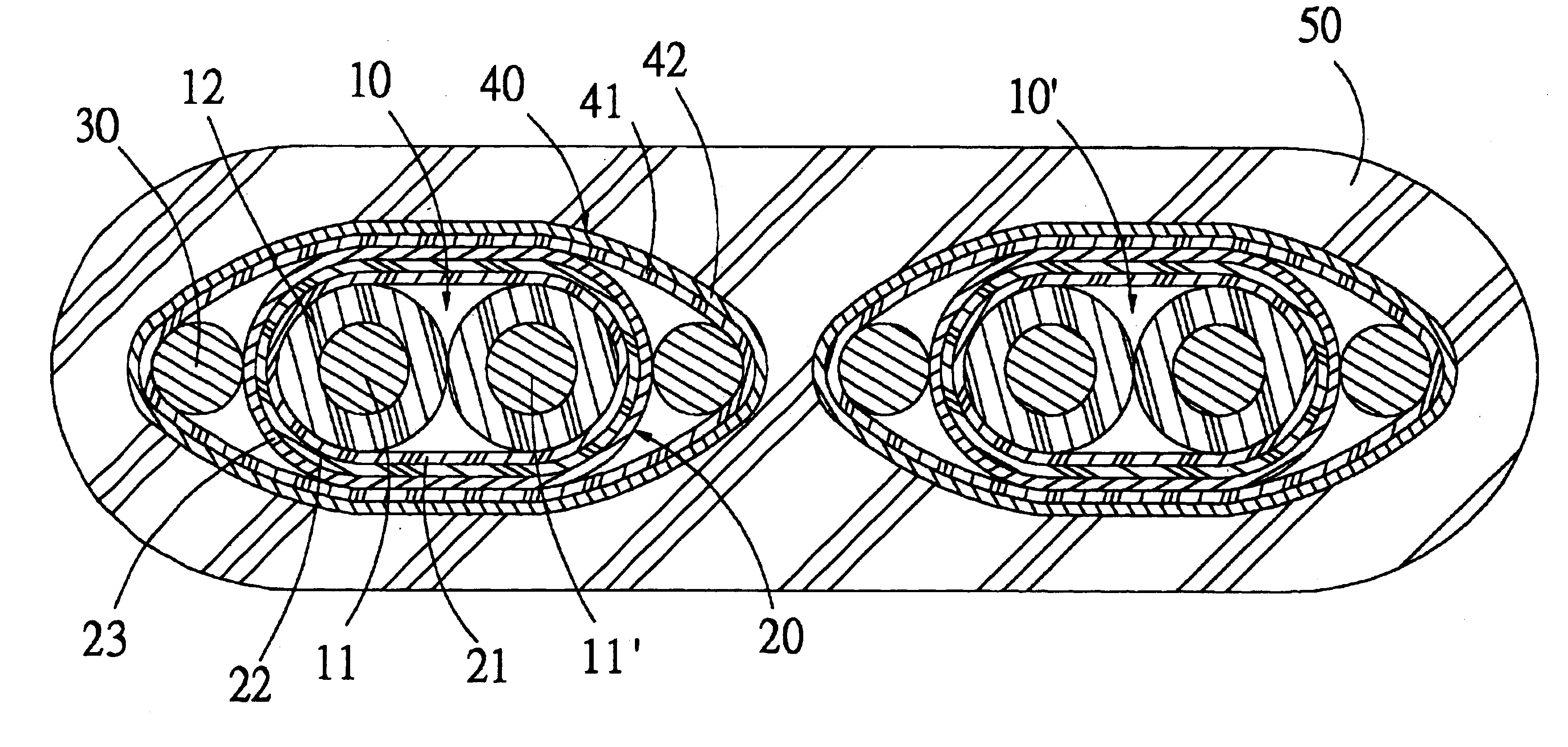
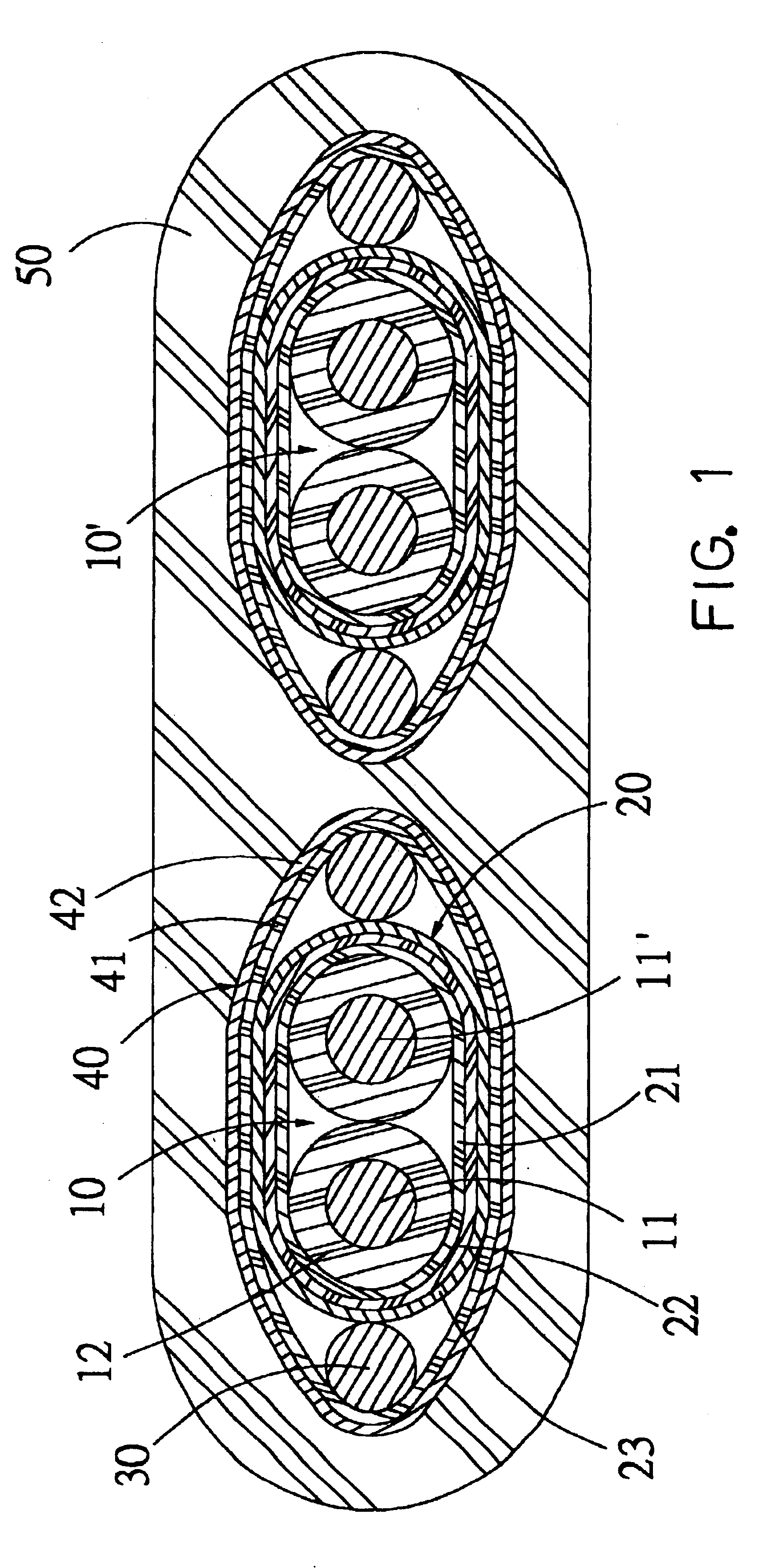
Referring to FIG. 1, shows a sectional view of a transmission cable according to the present invention in an embodiment thereof. As shown in FIG. 1, a transmission cable structure comprises one or more propagation channel sets 10, 10' for carrying out communication of electric appliances, a respective first covering 20 for location and forming a electrical shield to each propagation channel set 10, 10', a pair of drain wires 30 disposed outer side of the first covering 20 and a second covering 40 disposed outer side of the first covering 20 and the drain wires 30 for forming a electrical shield, and a jacket 50, being an outermost layer for protecting the cable. Therefore, to secure the pair of conductors 11, 11' being juxtaposed by location of the first covering 20 and flush with each other for avoiding signals transmitted in the conductors 11, 11' becoming asymmetry due to inconsistent lengths resulting from the cable being bent, and forming a double shield space by the first cove...


PUM


Abstract

A transmission cable structure includes one or more propagation channels. Two insulated conductors in each of the propagation channels are joined to each other tightly as a single piece, a first cover and at least one drain wire disposed outside each of the propagation channels for location and shield, a second covering and a jacket enclosed outside the first cover and the drain wire for forming electrical shield. Therefore, the two insulated conductors joined to each other tightly can ensure the symmetry of the transmission signal, also can prevent noise effectively and the electromagnetic wave of different loops by the double shield spaces formed by the first covering and the second covering in the transmission cable, so as to improve the transmission quality of the electronic signal.

Description

BACKGROUND OF THE INVENTION1. Field of the InventionThe present invention relates to a transmission cable structure and, in particular, to a transmission cable structure used in high frequency transmission system, which can restrain loop noise and ensure the symmetry of transmission cable.2. Description of Related ArtDue to functions of the central processing unit of a computer having been upgraded, the net bandwidth increasing and storage medium data rising tremendously, both the input and output interfaces of the periphery are getting necessary to provide larger bandwidth so that the standard for wide band transmission cables are regulated largely like bamboo shoots after spring. However, problems, such as transmission delay, impedance matching, cross talk, and ground noise control and electromagnetic wave radiation interference, resulting from high frequency signals are getting serious in the transmission cables along with the increased bandwidths of the transmission cables.As fo...

Claims


Application Information

Patent Timeline
IPC IPC(8): H01B7/08
CPCH01B7/0861H01B7/0876
Inventor CHANG, CHE-CHIA
Owner ING SHANG LUN
Why Eureka
Try Eureka