Waste heat recovery system

a heat recovery and waste technology, applied in the field of low cost systems, can solve the problems of high cost to generate useful thermal or power output, remote from any useful thermal load, etc., and achieve the effect of blocking heat loss and high efficiency system

Inactive Publication Date: 2004-06-01
ENERGENT CORP
View PDF6 Cites 37 Cited by
  • Summary
  • Abstract
  • Description
  • Claims
  • Application Information

AI Technical Summary

Benefits of technology

Typically, the blower is of induction type, having an inlet to which the mixed gas stream is supplied after passage through the vaporizer, i.e. the system operates by suction induced stream flow through the vaporizer, such suction also being utilized to induce mixing of the hot gas and cooler gas, in the ducting upstream of the vaporizer. A highly efficient system is thereby achieved.
Another object of the inv...

Problems solved by technology

However, some sources of waste heat have characteristics that result in excessively high costs to generate useful thermal...

Method used


Image

  • Waste heat recovery system
  • Waste heat recovery system
  • Waste heat recovery system

Examples


Embodiment Construction

Indirect Waste Heat Recovery System

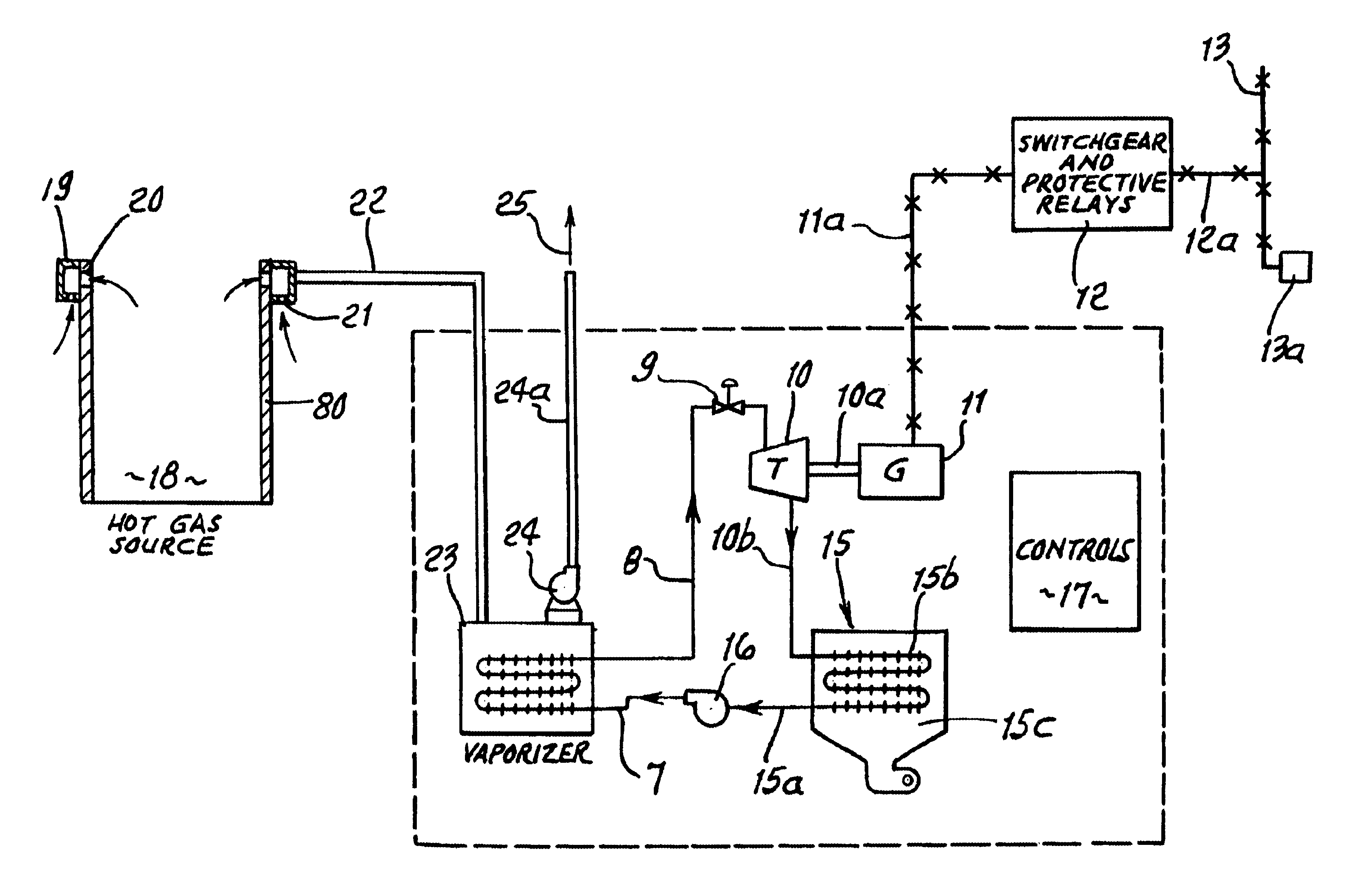
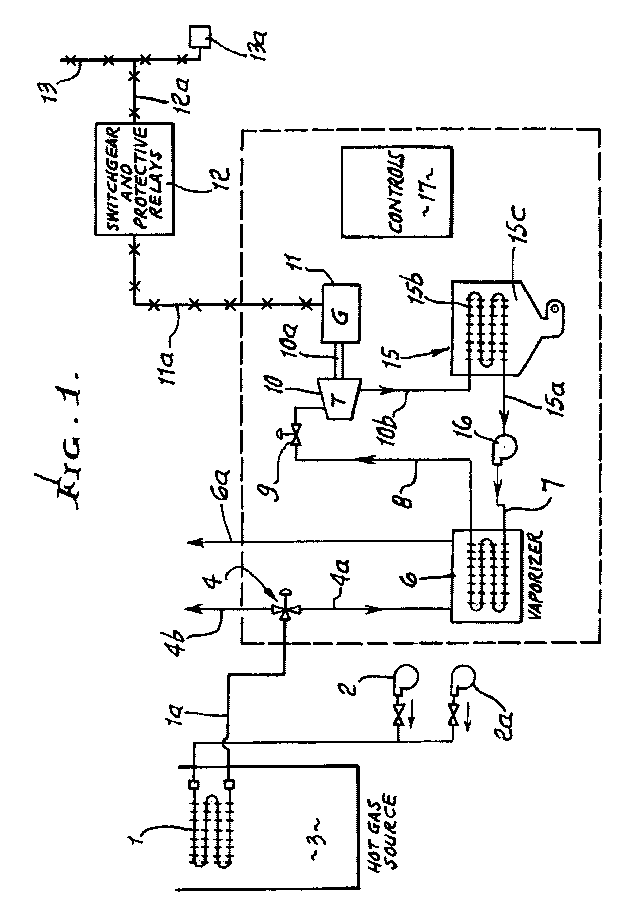
An indirect waste heat removal system is illustrated in FIG. 1. A heat exchanger 1, with the example having finned tubes, is installed in a hot gas source 3. Air is passed through the heat exchanger by a blower 2. A second blower 2a, can be provided so that if the first blower fails, uninterrupted heat removal and heat exchanger cooling can be provided.

The heated air flows through ducting 1a, to a diverter valve 4. For times when power is being generated or heat is being used, the diverter valve is positioned so that the hot air is ducted at 4a to the thermal load. During times when the power system or thermal load is not operating, the diverter valve ducts at 4b the heated air to atmosphere, enabling the heat exchanger structure temperature to remain at its operating value.

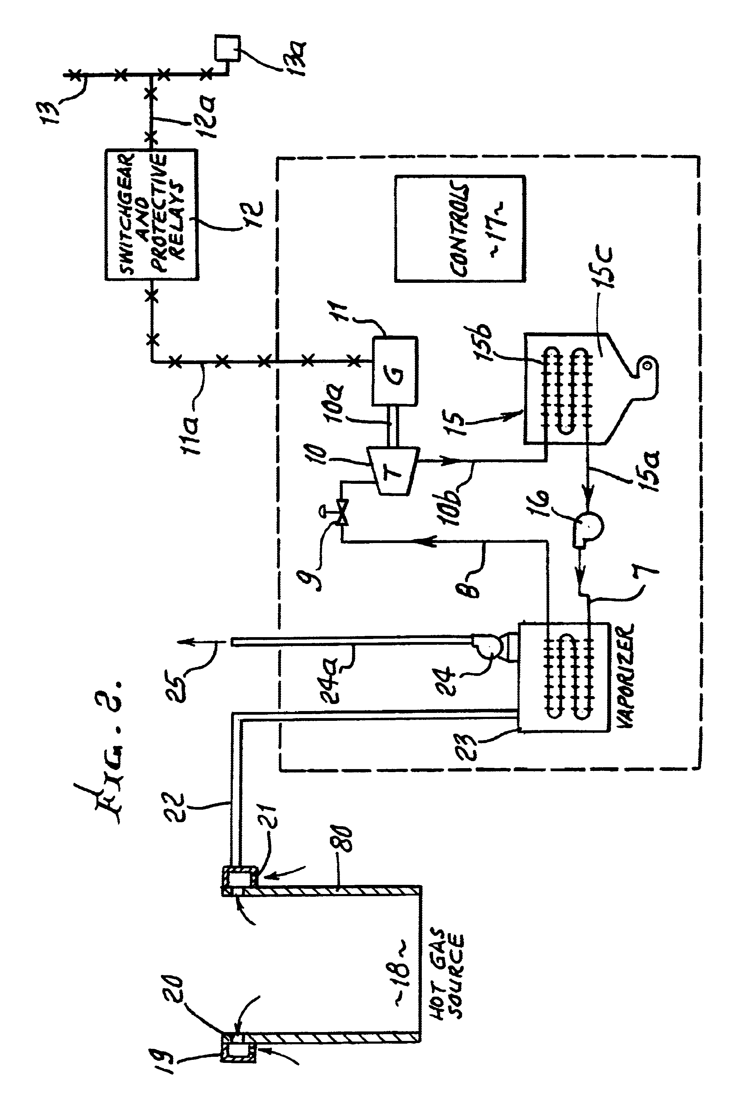
For the generation of power, a vaporizer or boiler 6, is provided. The hot air passes through the vaporizer, transferring heat to a working fluid such as water, hydrocarbons or ...


PUM


Abstract

A waste heat recovery system comprising ducting to which hot gas is communicated, means to supply lower temperature diluent gas to the ducting, to mix with the hot gas, and produce a reduced temperature mixed gas stream, a vaporizer in communication with the ducting, to receive the stream and to transfer heat from the stream to a working fluid in the vaporizer to vaporize said fluid, and a blower operating to displace the stream through the vaporizer.

Description

BACKGROUND OF THE INVENTIONThis invention relates generally to a low cost system to utilize waste heat produced in a process.Recovery of waste heat from combustion sources is an important way to achieve energy conservation that is widely practiced in industry. The waste heat can be used to provide useful heat to a process or to generate power using a heat engine. Some examples are regenerative heating in a glass furnace, generation of hot water for heating from an engine exhaust and generation of steam for power generation from the exhaust of a large gas turbine. However, some sources of waste heat have characteristics that result in excessively high costs to generate useful thermal or power output. These include low temperature, small size, remote location and / or corrosive products. Some examples include landfill gas flares and engine generators which are remote from any useful thermal loads.Accordingly, there is need for a low cost, efficient method to recovery the waste heat from...

Claims


Application Information

Patent Timeline
IPC IPC(8): F01K3/00F01K3/18
CPCF01K3/185
Inventor HAYS, LANCE G.BERGMANN, DUANE
Owner ENERGENT CORP
Why Eureka
Try Eureka