Microfluid driving device

a driving device and microfluid technology, applied in the direction of positive displacement liquid engines, laboratory glassware, instruments, etc., can solve the problems of difficult to clean up all residual samples or biochemical reagents of another experiment, high preparation cost of micropump, and inability to fit micropump in disposable chips

Inactive Publication Date: 2004-06-01
IND TECH RES INST
View PDF10 Cites 45 Cited by
  • Summary
  • Abstract
  • Description
  • Claims
  • Application Information

AI Technical Summary

Benefits of technology

Another objective of this invention is to provide a microfluid driving device that is simplified and is easy to prepare.

Problems solved by technology

In such a mechanical microfluid driving system provided with moveable elements and with a complicated structure, it is very difficult to clean up all residuals of samples or biochemical reagents of another experiment.
However, both the embedded rotational micropump and the embedded peristaltic micropump have complicated process of manufacture and expensive customer design components, which made the preparation costs of the micropump relatively high.
Such a micropump is not suited in disposable chips.
Such a requirement involves complicated structure, complicated operations and higher costs.
Furthermore, it is even more difficult to prepare a pump or pump module that provides driving forces back and forth in the microchannel.
However, the objects moved by the electro-osmosis force or the electrophoresis force are the charge-containing particles in the solution, not the solution itself.
From the process point of view, the electrode micropump is simple in structure, low in manufacture cost but limited in application.
It is not possible to introduce samples or reagents into empty channels.
Secondly, the distance that an EHD pump can drive a microfluid is limited.
Neither of these pumps provides satisfactory pumping effects.
In addition, these pumps may only work in microchannels with tiny diameter, e.g., 100 .mu.m and a voltage difference of hundreds to thousands of volt must be generated within a short distance.
High operation costs are thus caused.
When the ion concentration of the solution varies during the reaction, driving of the solution will become more difficult to control.
The problem is the interface between the servo system and the chip, the "system-to-chip interface".

Method used


Image

  • Microfluid driving device
  • Microfluid driving device
  • Microfluid driving device

Examples


example

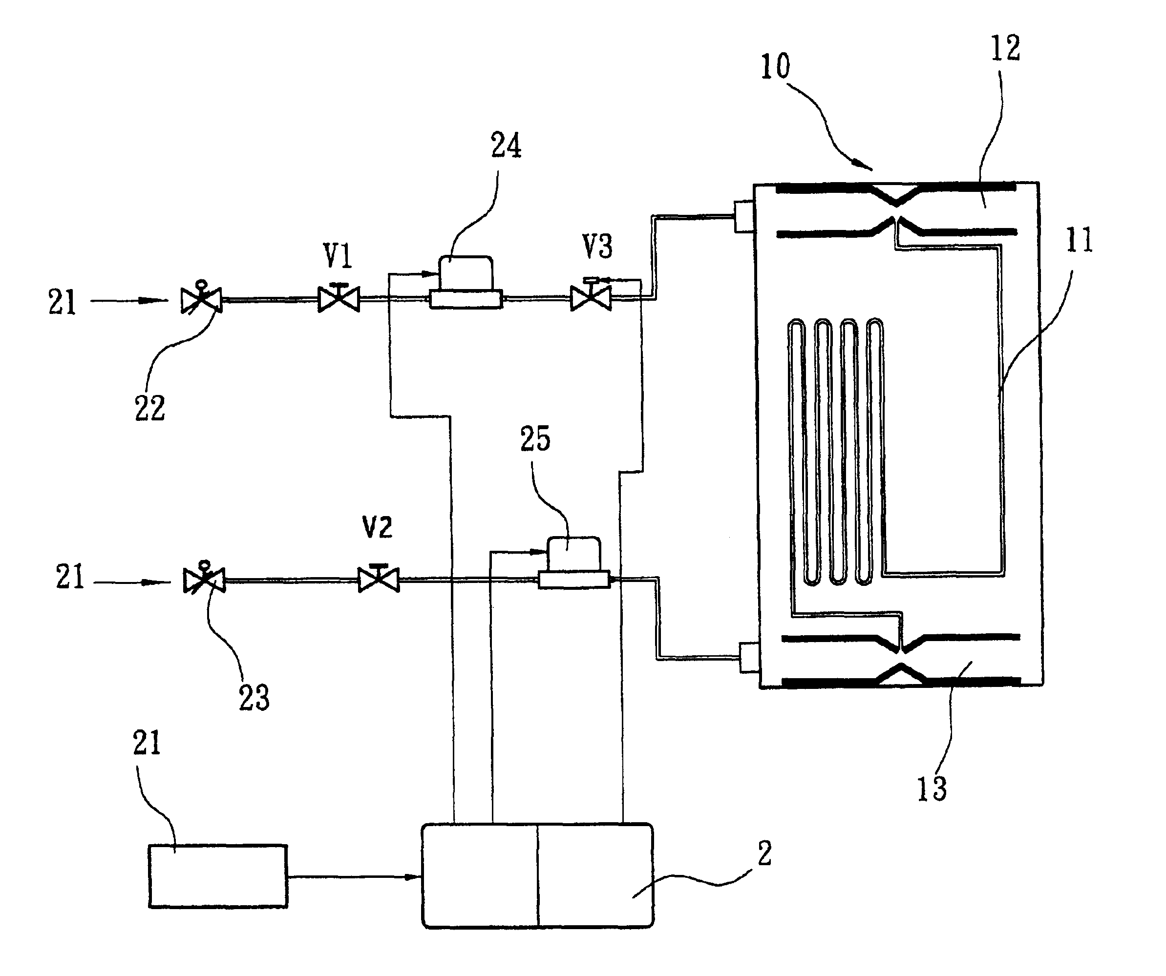
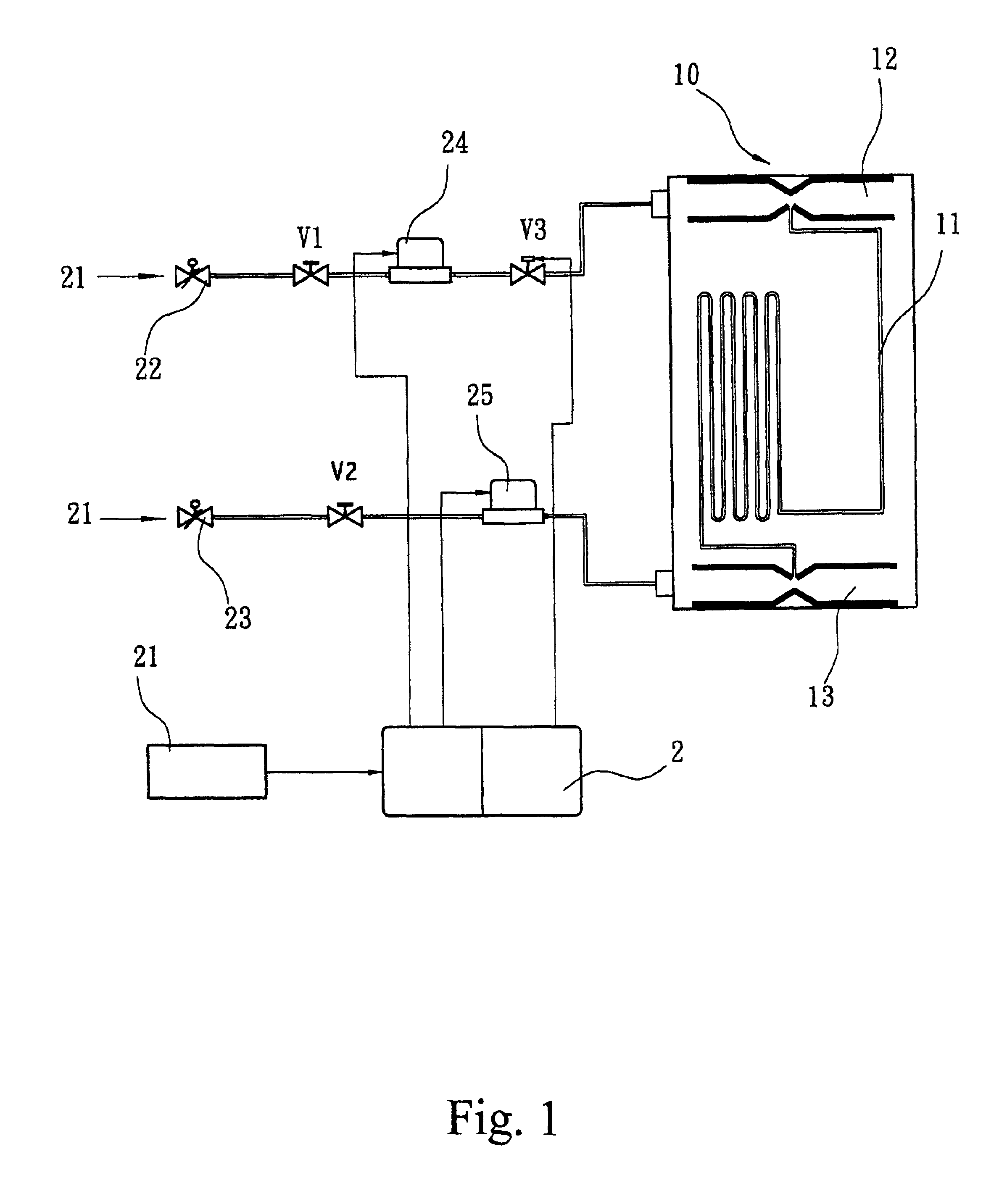
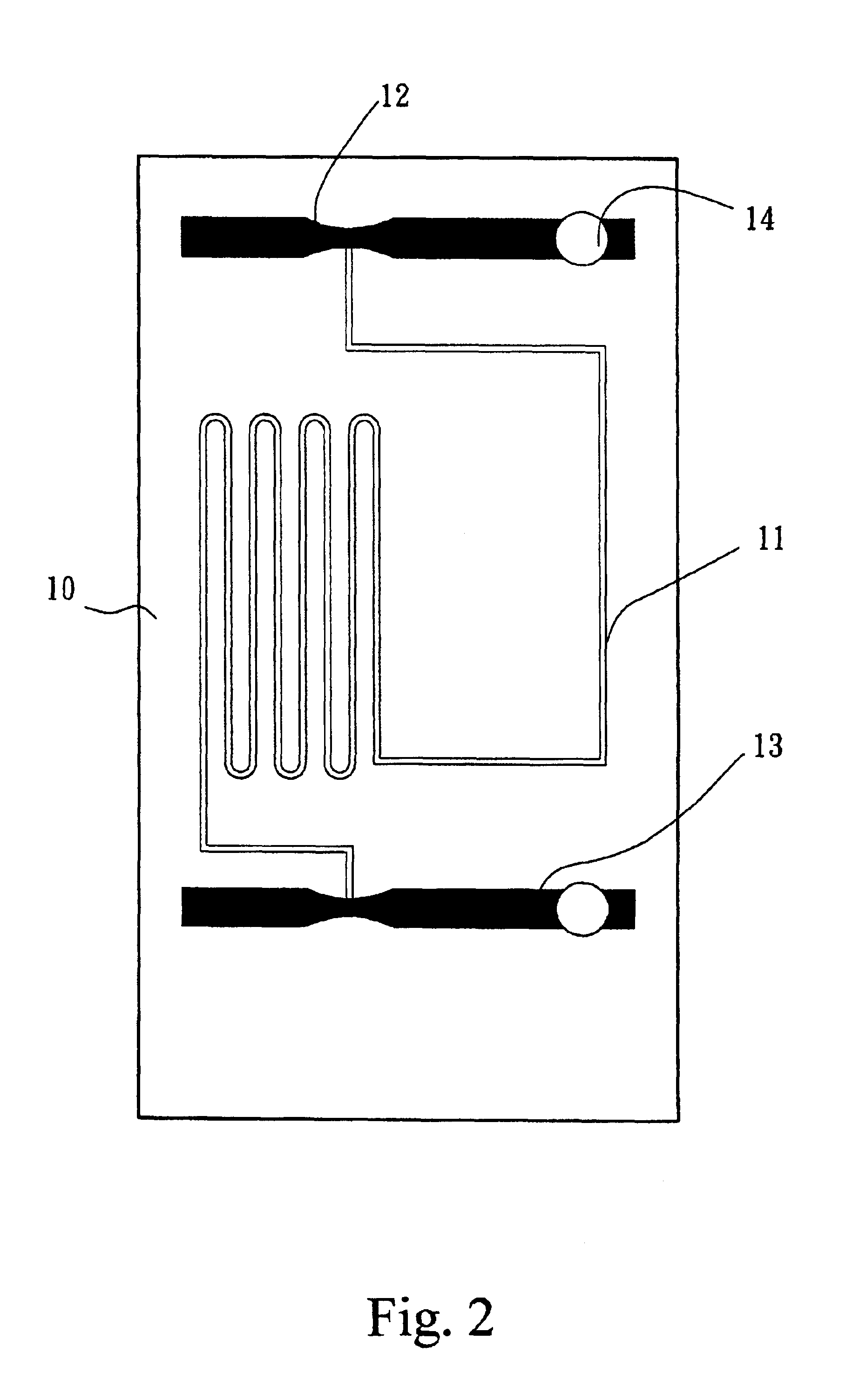
A chip having a microchannel and two Venturi pumps connected to both terminals of the microchannel is prepared. The specification of the device is:

Size of chip: 30 mm(L)*15 mm(W)*525 .mu.m(H).

Venturi pump: Airflow inlet sized 2 mm(W)*300 .mu.g m(D). After 3 mm from the inlet an inward declination of 25.degree. is formed until size of the channel to be 1.0 mm(L)*1.0 mm(W)*300 .mu.m(D). Then an outward declination of 10.degree. is formed until size of the channel to be 2 mm(W)*300 .mu.g m(D) as outlet. Opening at connection of the Venturi pump and the microchannel is sized 300 m(W)*300 .mu.m(D).

Microchannel: 300 .mu.m(W)*300 .mu.m(D)*15 cm (L).

Testing fluid: Blue ink, about 4.3 .mu.l.

A silicon-glass plate of 30 mm(L)*15 mm(W)*1.0 mm(T) is prepared. An inlet is prepared at the upper Venturi pump. The testing fluid is filled into the inlet and is introduced into the microchannel by the surface tension of the fluid, until the force is balanced. Supply airflow to the bottom Venturi pump t...


PUM


Abstract

A microfluid driving device is provided. The microfluid driving device of this invention comprises microfluid driving platform prepared in a chip, which platform comprises at least two miniature Venturi pumps, at least one microchannel and optionally micro mixers or micro reactors in said microchannel; an external pneumatic flow supply and control module that provides selectively different air flows; and an interface device connecting said microfluid driving platform and said external pneumatic flow supply and control module. The air flows supplied by said the pneumatic flow supply and control module are supplied under selected flow rates and frequencies to said at least two Venturi pumps through said interface device, such that the microfluid inside said microchannel may be driven forward or backward or halt and the transportation, mixing and reaction of the microfluid may be accomplished.

Description

The present invention relates to a microfluid driving device, especially to a non-contact pneumatic microfluid driving device comprising an external servo system and a chip carrying a microfluid driving platform.BACKGROUND OF INVENTIONThe "biochip" which is able to automatically operate the nucleic acid sample processing and the testing of base series has been developing in all countries the world. In these biochips, the microfluid driving system that drives microfluid that contains samples of biochemical agents to move inside microfluidic channels is one of the most important equipments. The question of how to easily control fluid movement and avoid the cross pollution of the sample or the biochemical agents with the driving system, as become a question of interest.The microfluid driving system that are known to the public may be divided into three classes. They are the on-chip mechanical micropump, the on-chip electrokinetic micropump and the external servo system. Descriptions th...

Claims


Application Information

Patent Timeline
Patent Type & Authority Patents(United States)
IPC IPC(8): B01L3/00F04F5/54F04B19/00F04F5/00
CPCB01F15/0248B01F15/0284B01L3/50273F04B19/006F04F5/54B01F13/0059B01L2400/0463Y10T436/25Y10T436/2575Y10T436/15B01L2400/0487B01F33/30B01F35/717614B01F35/75441
Inventor CHUNG, CHEN-KUEICHANG, WEI-JIEHHSIAO, CHIEH-LINGWENG, KUO-YAO
Owner IND TECH RES INST
Why Eureka
Try Eureka