Device including a combustion engine, a use of the device, and a vehicle

a combustion engine and combustion engine technology, applied in the direction of electric devices, machines/engines, propulsion parts, etc., can solve the problems of large energy loss, mechanical resonance, and reduce the positioning accuracy of each additional mechanical arrangement, so as to improve the control of the combustion engine and high efficiency

Inactive Publication Date: 2004-06-15
VOLVO TECH
View PDF18 Cites 89 Cited by
  • Summary
  • Abstract
  • Description
  • Claims
  • Application Information

AI Technical Summary

Benefits of technology

is to provide a combustion engine with a high efficiency. Furthermore, it is aimed at improved control of a combustion engine.
According to an embodiment of the invention, the control unit is arranged to control the size of the effect. Thus, the control possibilities are further improved with regard to the determination of the instantaneous position of the piston. Preferably, the control unit is arranged to control the size of the effect in a continuous manner.

Problems solved by technology

However, the connecting rod and the crank shaft form an extensive arrangement of shaft lines, which can cause a mechanical resonance.
The transfer of energy from the pistons to the driving wheels of the vehicle via the arrangement including the connecting rods and the crank shaft results in radial forces, large energy losses and, reduces positioning accuracy for each additional mechanical arrangement which is required.
Consequently, the possibilities to vary the compression during operation are limited.
The commutator is subject to wear and has a limited life time.
The electric generator lacks a soft magnetic flow carrier, which means that a relatively low efficiency is obtained.
However, this electric generator lacks soft magnetic flow carriers.

Method used


Image

  • Device including a combustion engine, a use of the device, and a vehicle
  • Device including a combustion engine, a use of the device, and a vehicle
  • Device including a combustion engine, a use of the device, and a vehicle

Examples


Embodiment Construction

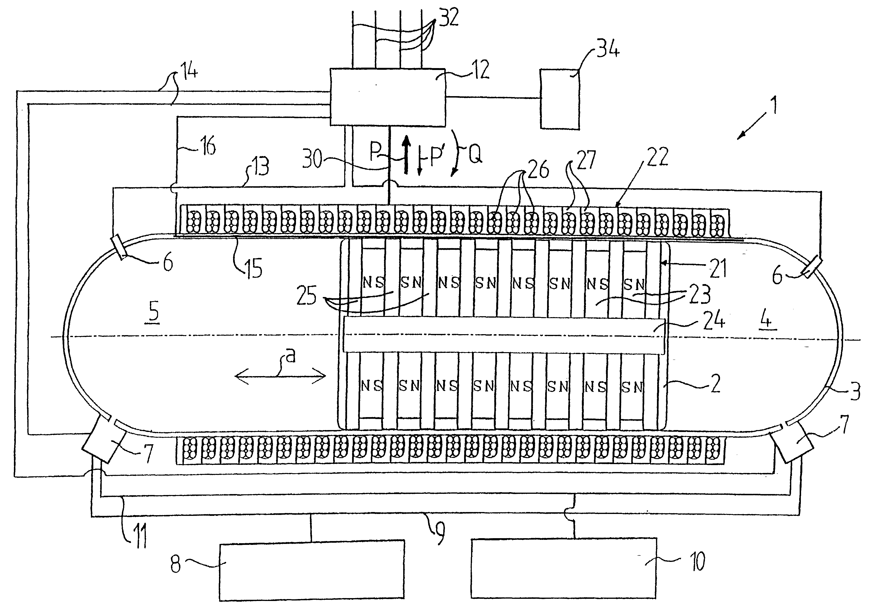
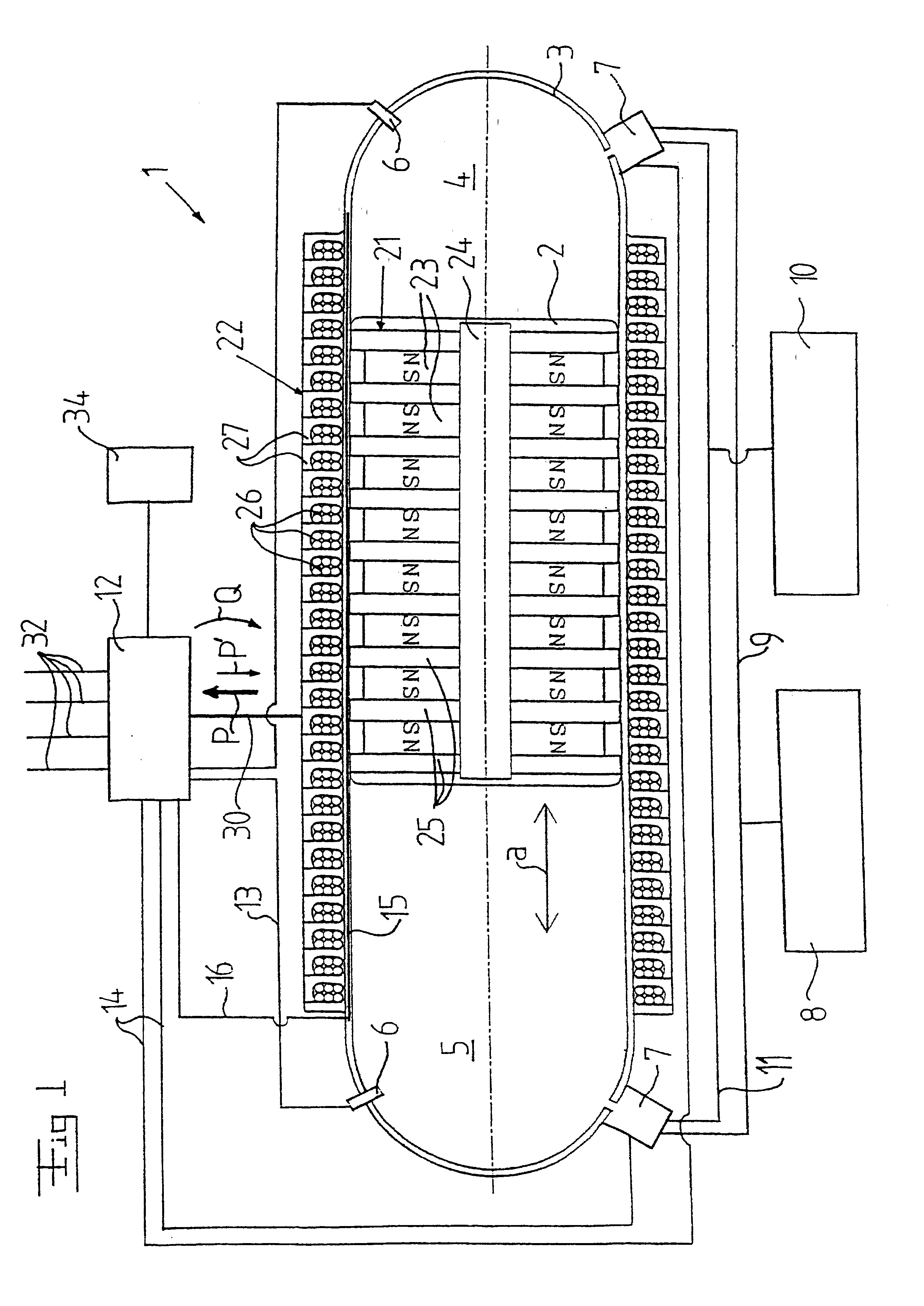
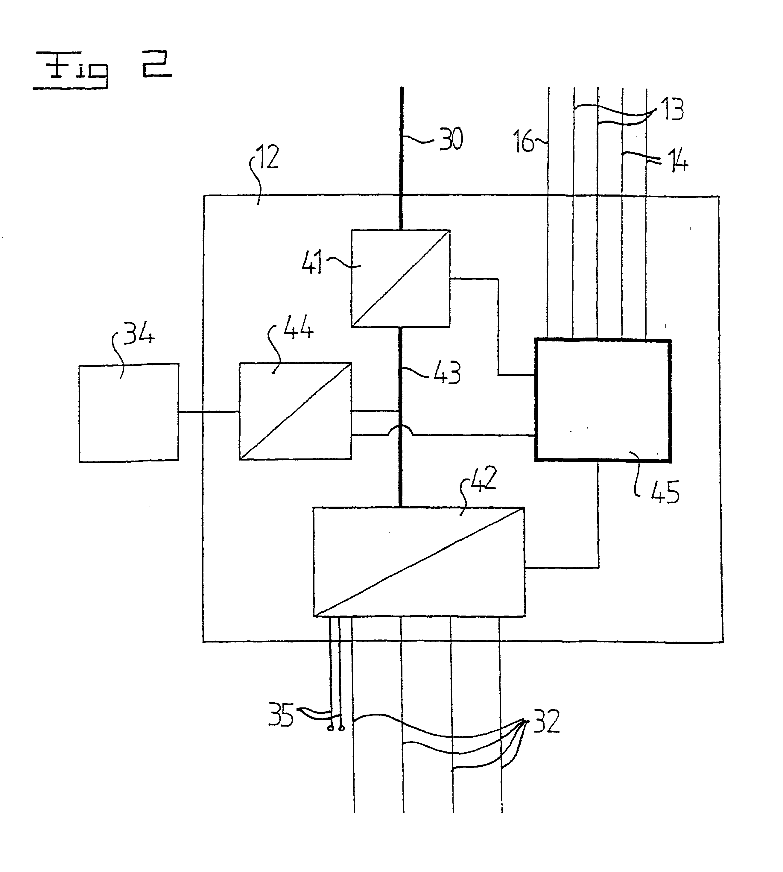
FIG. 1 discloses a device according to the present invention. The device includes a combustion engine 1 with a piston 2, which is mechanically freely moveable in a housing 3. In the example disclosed, the housing 3 has a cylindrical shape. The piston 2 may move in a rectilinear reciprocating movement in the housing 3 in the movement direction a. The housing 3 also may have an extension, which is not rectilinear but bow-shaped. The piston 2 is mechanically freely moveable in the housing such that it is loosely provided in the housing 3, i.e. it is not mechanically connected to any element for the transfer of a force, for instance, via a connecting rod and a crank shaft. In the example disclosed, a combustion engine 1 with a housing 3 and a piston 2 is disclosed. However, it is to be noted that a combustion engine within the scope of the present invention also may include more than one housing and one piston. To increase the possible effect from the combustion engine 1 or improve the ...


PUM


Abstract

A device that includes a combustion engine with a piston that is mechanically freely movable in a housing. The device permits combustion of a fuel mixture to produce a pushing force to the piston. The device includes an electromagnetic energy transducer and an external current circuit, which is connected to the energy transducer for exchange of effect in a direction to or from the energy transducer. A control unit controls the direction of the effect, which is exchanged between the energy transducer and the external current circuit, during operation of the device. Such a device can be used to generate electrical energy, and can be employed in a vehicle.

Description

1. Field of the InventionThe present invention refers to a device including a combustion engine with a piston mechanically freely movable in a space in a housing, where the device permits combustion of a fuel mixture to produce a pushing force to the piston, an electromagnetic energy transducer, and an external current circuit connected to the energy transducer for exchange of effect in a direction to or from the energy transducer. The invention also refers to a use of the device, and a vehicle.2. Discussion of the Related ArtA known driving source for motor vehicles, such as private cars, buses and trucks, is combustion engines with internal intermittent combustion. Combustion engines are used also in other contexts, such as for garden machines, contractor machines etc., and for generating an electric effect (a so called diesel-driven generating set). The combustion engine normally has one or several pistons moving reciprocally in a cylinder housing. The rectilinear movement of the...

Claims


Application Information

Patent Timeline
Patent Type & Authority Patents(United States)
IPC IPC(8): F02B1/12F02B1/00F02B71/00F02B71/04H02K7/18B60W20/00B60K6/46B60W10/08F02D45/00H02K35/02H02K41/03
CPCB60K6/46F02B71/04H02K7/1884B60L11/005B60L11/126B60L11/16B60L15/2045F02B1/12B60L2260/28F02B63/041Y02T10/6217B60L2210/10B60L2210/30B60L2210/40B60L2220/46B60L50/30B60L50/40B60L50/62Y02T10/62Y02T10/64Y02T10/70Y02T10/72Y02T10/7072
Inventor MALMQUIST, ANDERSGERTMAR, LARSFRANK, HARRYSADARANGANI, CHANDUR
Owner VOLVO TECH
Why Eureka
Try Eureka