Universal energy regulating controller circuit

a controller circuit and energy regulation technology, applied in the direction of motor/generator/converter stopper, electric motor speed/torque regulation, dynamo-electric converter control, etc., can solve the problem of system over-design, motor over-design, and actual applied voltage, i.e., the real component of the complex ac voltag

Inactive Publication Date: 2004-06-22
INT CONTROLS & MEASUREMENT
View PDF15 Cites 44 Cited by
  • Summary
  • Abstract
  • Description
  • Claims
  • Application Information

AI Technical Summary

Benefits of technology

It is an object of this invention to provide AC power to an AC load, such as a motor armature, in a way that avoids the drawbacks of the prior art, as mentioned above.
The drive circuit of this invention is of a simple, straightforward design, being inherently compact and relatively inexpensive, and at the same time avoiding energy waste.

Problems solved by technology

The motor armature, which is basically an inductive load, may have to face an unfavorable power factor, which means that the actual applied voltage, i.e., the real component of the complex AC voltage, may become unacceptably low.
This means that the system has to be over-designed to meet full load requirements at low voltage.
This means that, according to conventional practice, the motor has to be over-designed by at least 19%.
Consequently, at normal or high line conditions, over 20% of the electric energy is wasted.
Unfortunately, the use of PWM can lead to other problems, including winding insulation failure in the motor armature.
PWM operation can also result in high switching losses, as well.
Not only does this consume power in operation, but the constant charging and discharging of the large power capacitors in the ASD system can limit their useful life.
In many cases, what is needed is to simply modify the existing line AC waveshape to achieve the improved power factor or to boost (or regulate) the effective RMS voltage, but with the ASD system, this is not possible.
While this saves the motor, it can cause severe problems for the system that the motor is designed to drive.
If the brownout lasts for a period of an hour or more, the meat may begin to spoil, or the ice cream may melt.
However, that has not been possible with existing power control circuits.

Method used


Image

  • Universal energy regulating controller circuit
  • Universal energy regulating controller circuit
  • Universal energy regulating controller circuit

Examples


Embodiment Construction

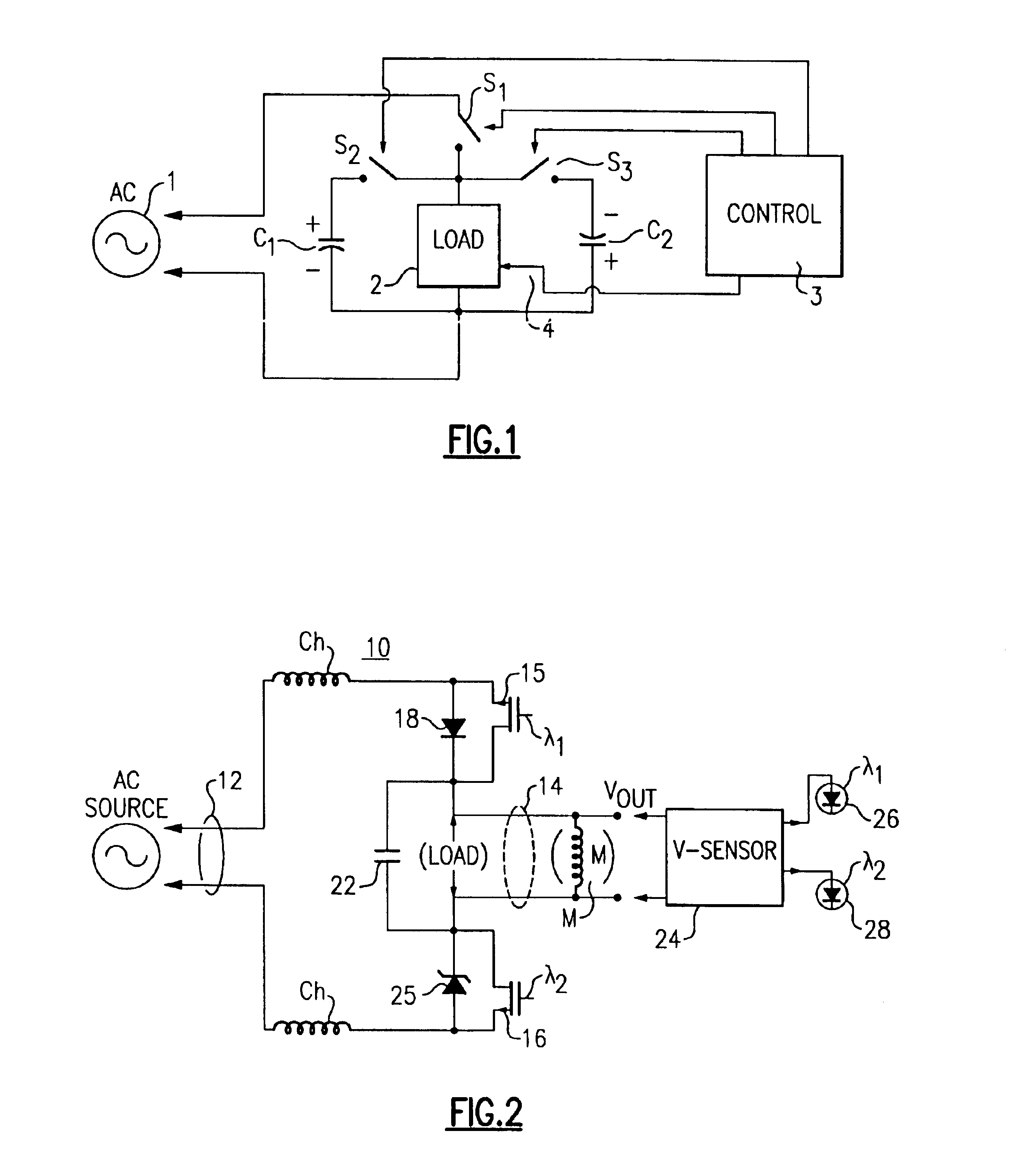
With reference to the Drawing, FIG. 1 is a basic schematic view of a circuit employing the general concepts of this invention, and receiving AC power from a source 1 and applying it to a load 2. A first controlled switch S1 is interposed between the source and the load 2, and there are also second and third controlled switches S2 and S3 that are selectively opened and closed for charging first and second capacitors C1 and C2. A control circuit 3 applies switching signals to the controlled switches S1, S2, and S3, and may have a sensor input 4 coupled to the load 2.

With this arrangement, the capacitors C1 and C2 can be kept charged up to peak AC voltage, which is typically about 40% higher than the average or RMS line voltage value. The line voltage can be switched on or off to the load 2 as needed, by opening and closing the switch S1, and the stored charge can be applied from the capacitors C1 and C2 to the load 2 by selectively opening and closing the switches S2 and S3. In practi...


PUM


Abstract

A power controller for applying power to an induction motor or similar AC load has a variable drive circuit for staring and switching a portion of the AC input line power. In one mode, the input line power is fed straight through to the load. In another mode, the AC waveform is reshaped to improve the power factor or to boost its RMS value, e.g., for brownout protection. In a further mode the output power can be provided at a different frequency from the input line power. Vector control increases efficiency through power optimization, with sensing of load requirements. Sensing of regeneration pulses at the commencement of a half cycle can be employed for direct sensing of motor speed or load.

Description

The present invention relates to drive circuits that provide AC power (or in some cases DC power) to a motor armature or other AC load or to a reversing load, and is more particularly directed to a control circuit that provides AC power at a frequency, wave shape, and power factor that is tailored for an AC or inductive load that may vary during use, such as a single-phase AC induction motor, an example of which is a motor used to drive a compressor or blower in a HVAC application. The invention is more specifically concerned with a control circuit for applying drive power to a motor which may be from fractional horsepower to several horsepower or above in size; in which a torsional load varies depending upon external factors, and in which the motor torque can depend on the condition or quality of the AC line power; and in which the applied line voltage can drop from a nominal 117 volts (RMS) to below 100 volts, in which the power factor or phase angle can be significant; and in whi...

Claims


Application Information

Patent Timeline
Patent Type & Authority Patents(United States)
IPC IPC(8): H02M5/02H02M1/00H02M5/293H02M1/42
CPCH02M1/4208H02M5/293H02M2003/1555Y02B70/126H02M3/1555Y02B70/10
Inventor KADAH, ANDREW S.
Owner INT CONTROLS & MEASUREMENT
Why Eureka
Try Eureka