Optical device having a wide field-of-view for multicolor images

a multi-color image and optical device technology, applied in the field of optical devices having a wide field-of-view for multi-color images, can solve the problems of not being able to easily miniaturize, heavy, bulky, etc., and achieve the limitation of the ability to provide sufficient information to the user, heavy weight of the crt display, and the effect of reducing the size of the active matrix panel

Inactive Publication Date: 2004-06-29
MIRAGE INNOVATIONS LTD
View PDF7 Cites 114 Cited by
  • Summary
  • Abstract
  • Description
  • Claims
  • Application Information

AI Technical Summary

Problems solved by technology

The CRT displays are heavy, bulky, and not easily miniaturized.
The active matrix panel uses a transistor to control each pixel, and is more expensive.
Small size real image displays have a relatively small surface area on which to present a real image, thus have limited capability for providing sufficient information to the user.
In other words, because of the limited resolution of the human eye, the amount of details resolved from a small size real image might be insufficient.
For example, such displays have suffered from being too heavy for comfortable use, as well as too large so as to be obtrusive, distracting, and even disorienting.
These defects stem from, among other things, the incorporation of relatively large optics systems within the mounting structures, as well as physical designs which fail to adequately take into account important factors as size, shape, weight, etc.
A common problem to all types of holographic optical elements is their relatively high chromatic dispersion.
This is a major drawback in applications where the light source is not purely monochromatic.
Another drawback of some of these displays is the lack of coherence between the geometry of the image and the geometry of the holographic optical element, which causes aberrations in the image array that decrease the image quality.
New designs, which typically deal with a single holographic optical element, compensate for the geometric and chromatic aberrations by using non-spherical waves rather than simple spherical waves for recording; however, they do not overcome the chromatic dispersion problem.
Moreover, with these designs, the overall optical systems are usually very complicated and difficult to manufacture.
Furthermore, the field-of-view resulting from these designs is usually very small.
As known, angular color aberration and / or loss of resolution, are often caused by a change in the exit angle relative to the entry angle.

Method used


Image

  • Optical device having a wide field-of-view for multicolor images
  • Optical device having a wide field-of-view for multicolor images
  • Optical device having a wide field-of-view for multicolor images

Examples


example 1

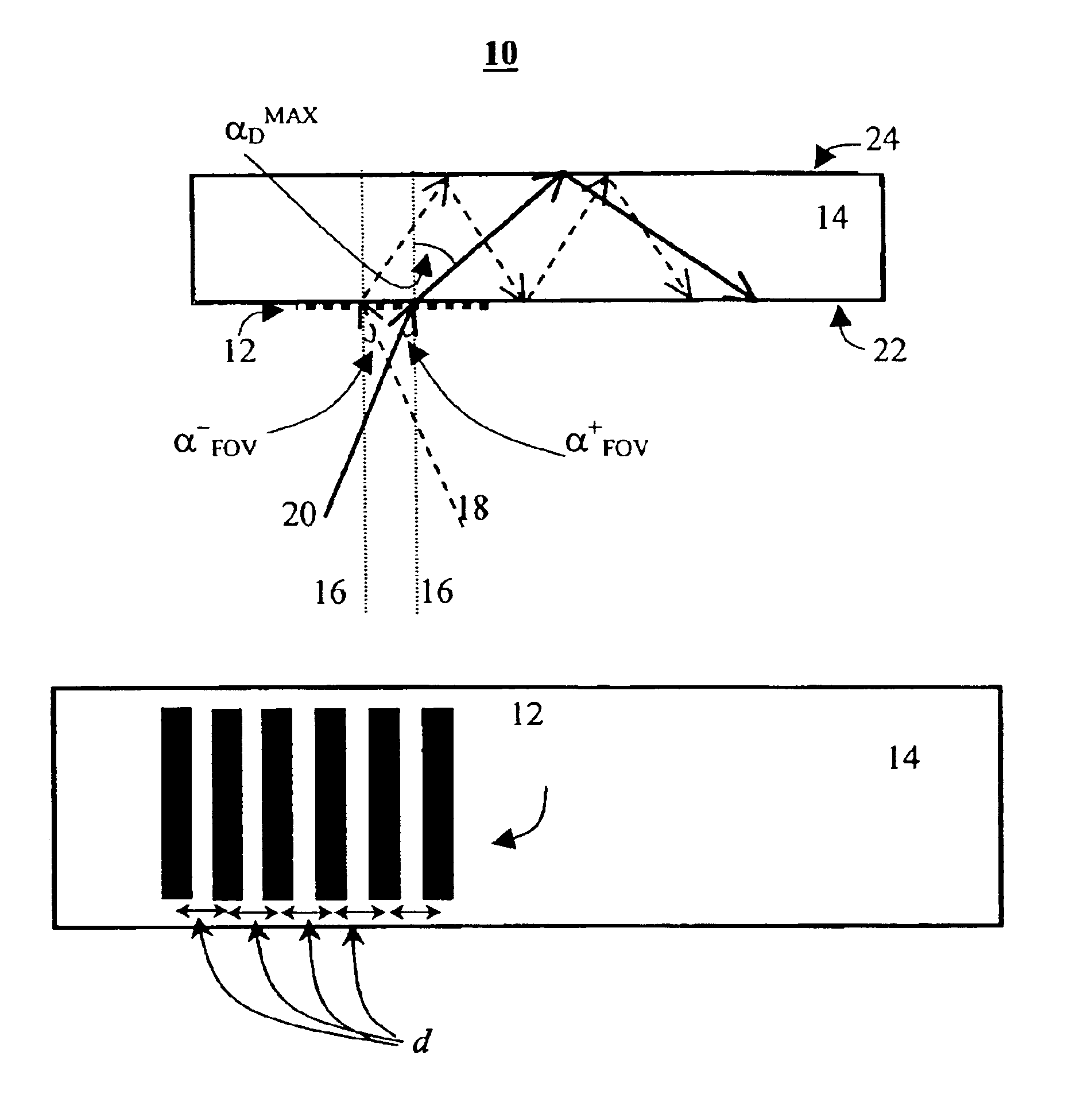
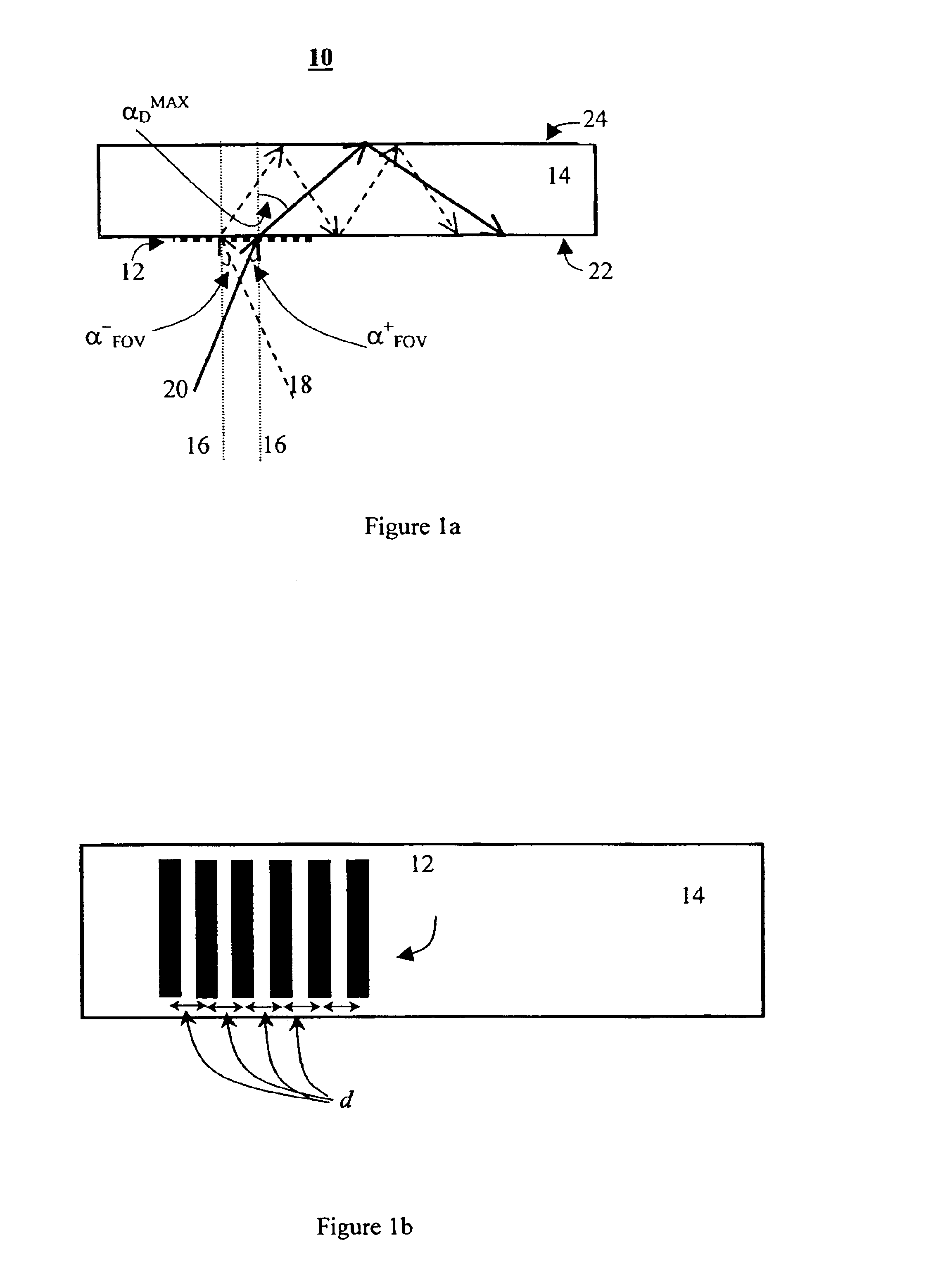
Determination of the Grating Pitch

As already stated, the grating pitch, d, depends on the required field-of-view and the wavelength of the light and independent of the index of refraction of the substrate, or any other dimensional parameter of the substrate, and it is conveniently determined from the formula d=.lambda..sub.B / (1-n.sub.A sin .alpha..sup.-.sub.FOV). In the following, n.sub.A is taken to be a unity.

For example, if the shortest wavelength in the spectrum corresponds to a blue light, e.g., .lambda..sub.B =480 nm, than for a first field-of-view angle of .alpha..sup.-.sub.FOV =-8.degree., the grating pitch should be d=421 nm, and for a larger first field-of-view angle of .alpha..sup.-.sub.FOV =-14.degree., the grating pitch should be d=386 nm.

example 2

Determination of the Minimal Refraction Index

The minimal index of refraction can be determined, as detailed above from the formula n.sub.MIN =(.lambda..sub.R / d-n.sub.A sin .alpha..sup.-.sub.FOV) / sin .alpha..sup.MAX.sub.D, where the maximal diffraction angle can be determined according to additional considerations, such as the "flat" embodiment and the "at least one hop" embodiment. Again, n.sub.A is taken to be a unity.

"Flat" Embodiment

According to the "flat" embodiment, it is required that all the diffraction angles would be below a predetermined angle. The present example corresponds to a maximal diffraction angle of 80 degrees.

Hence, if the spectrum ranges from a blue light (.lambda..sub.B =480 nm) to a red light (.lambda..sub.R =620 nm), than for field-of-view angles of .alpha..sup..+-..sub.FOV =.+-.14.degree., the minimal index of refraction is n.sub.MIN =1.877. An appropriate light-transmissive substrate is, for example a glass type SF 66 purchased from Schott Glas, Germany f...


PUM


Abstract

A diffractive optical element for guiding a light having a color spectrum characterized by a plurality of wavelengths longer than a shortest wavelength, lambdaB, and shorter than a longest wavelength, lambdaR, the light striking the diffractive optical element at an angle greater than a first field-of-view angle, alpha<->FOV, and smaller than a second field-of-view angle, alpha<+>FOV. The diffractive optical element comprising a linear grating being formed in a light-transmissive substrate. The linear grating is characterized by a pitch, d, selected so as to allow total internal reflection of a light having wavelength of lambdaB and a striking angle of alpha<->FOV. The light-transmissive substrate is characterized by an index of refraction, ns, larger than a minimal index of refraction, nMIN, which is selected so as to allow total internal reflection of a light having wavelength of lambdaR and a striking angle of alpha<+>FOV.

Description

FIELD AND BACKGROUND OF THE INVENTIONThe present invention relates to an optical device and, more particularly, to an optical device having a wide field-of-view and which is capable of providing multicolor images.Miniaturization of electronic devices has always been a continuing objective in the field of electronics. Electronic devices are often equipped with some form of a display, which is visible to a user. As these devices reduce in size, there is an increase need for manufacturing compact displays, which are compatible with small size electronic devices. Besides having small dimensions, such displays should not sacrifice image quality, and be available at low cost. By definition the above characteristics are conflicting and many attempts have been made to provide some balanced solution.An electronic display may provide a real image, the size of which is determined by the physical size of the display device, or a virtual image, the size of which may extend the dimensions of the ...

Claims


Application Information

Patent Timeline
Patent Type & Authority Patents(United States)
IPC IPC(8): G02B5/18G02B5/32
CPCG02B5/1847G02B5/1866
Inventor NIV, YEHUDANIVON, UZIA
Owner MIRAGE INNOVATIONS LTD
Why Eureka
Try Eureka