Methods and apparatus to improve the performance of universal electric motors

a technology of universal electric motors and motors, applied in the direction of electric controllers, motor/generator/converter stoppers, dynamo-electric converter control, etc., can solve the problems of low sensor cost, motor input power to stay constant, and controllers that cannot detect speed variations

Inactive Publication Date: 2004-07-06
SOUTHERN ILLINOIS UNIVERSITY
View PDF51 Cites 24 Cited by
  • Summary
  • Abstract
  • Description
  • Claims
  • Application Information

AI Technical Summary

Benefits of technology

An advantage of the invention is that it improves the performance of a motor by maintaining a constant RPM (Rotations per Minute) under varying load conditions. It can also extend the brush life of all universal, AC and DC, and commutator type DC motors while remaining inexpensive to manufacture and install. Additionally, it does not require costly modification to the motor.Another advantage of the invention is that it can directly replace existing speed control modules in products already out on the market as well as be easily installed in new products. It can also be used as an external and independent module that existing products can be easily connected to.All the disclosed embodiments of the invention disclosed herein can be made and used without undue experimentation in light of the disclosure. It will be appreciated by those skilled in the art that the invention may be practiced otherwise than as specifically described herein.Further, the individual components need not be formed in the disclosed shapes, or combined in the disclosed configurations, but could be provided in virtually any shapes, and / or combined in virtually any configuration. Further, the individual components need not be fabricated from the disclosed materials, but could be fabricated from virtually any suitable materials.Further, variation may be made in the steps or in the sequence of steps composing methods described herein.Further, although the speed control device described herein can be a separate module, it will be manifest that this motor speed control device may be integrated into the system with which it is associated. Furthermore, all the disclosed elements and features of each disclosed embodiment can be combined with, or substituted for, the disclosed elements and features of every other disclosed embodiment except where such elements or features are mutually exclusive.It will be manifest that various substitutions, modifications, additions and / or rearrangements of the features of the invention may be made without deviating from the spirit and / or scope of the underlying inventive concept. It is deemed that the spirit and / or scope of the underlying inventive concept as defined by the appended claims and their equivalents cover all such substitutions, modifications, additions and / or rearrangements.The appended claims are not to be interpreted as including means-plus-function limitations, unless such a limitation is explicitly recited in a given claim using the phrase(s) "means for" and / or "step for." Subgeneric embodiments of the invention are delineated by the appended independent claims and their equivalents. Specific embodiments of the invention are differentiated by the appended dependent claims and their equivalents.

Problems solved by technology

The problem with this technology is that it causes the motor input power to stay constant, regardless of the load on the motor.
The controller has no way of detecting speed variations.
The problem with this approach is that the sensors are expensive and it requires a detailed installation of the sensors and related equipment.
This results in a complicated machine to install and use.
However, these have been limited in their implementation.
Heretofore, the requirements of a simple motor speed control apparatus that is easy to install and use, which keeps the speed constant even under varying loads for an electric motor powered by an AC or DC power supply, and which utilizes a commutator and brushes have not been fully met.

Method used


Image

  • Methods and apparatus to improve the performance of universal electric motors
  • Methods and apparatus to improve the performance of universal electric motors
  • Methods and apparatus to improve the performance of universal electric motors

Examples


Embodiment Construction

The invention and the various features and advantageous details thereof are explained more fully with reference to the nonlimiting embodiments that are illustrated in the accompanying drawings and detailed in the following description. Descriptions of well known components and processing techniques are omitted so as not to unnecessarily obscure the invention in detail. It should be understood, however, that the detailed description and the specific examples, while indicating specific embodiments of the invention, are given by way of illustration only and not by way of limitation.

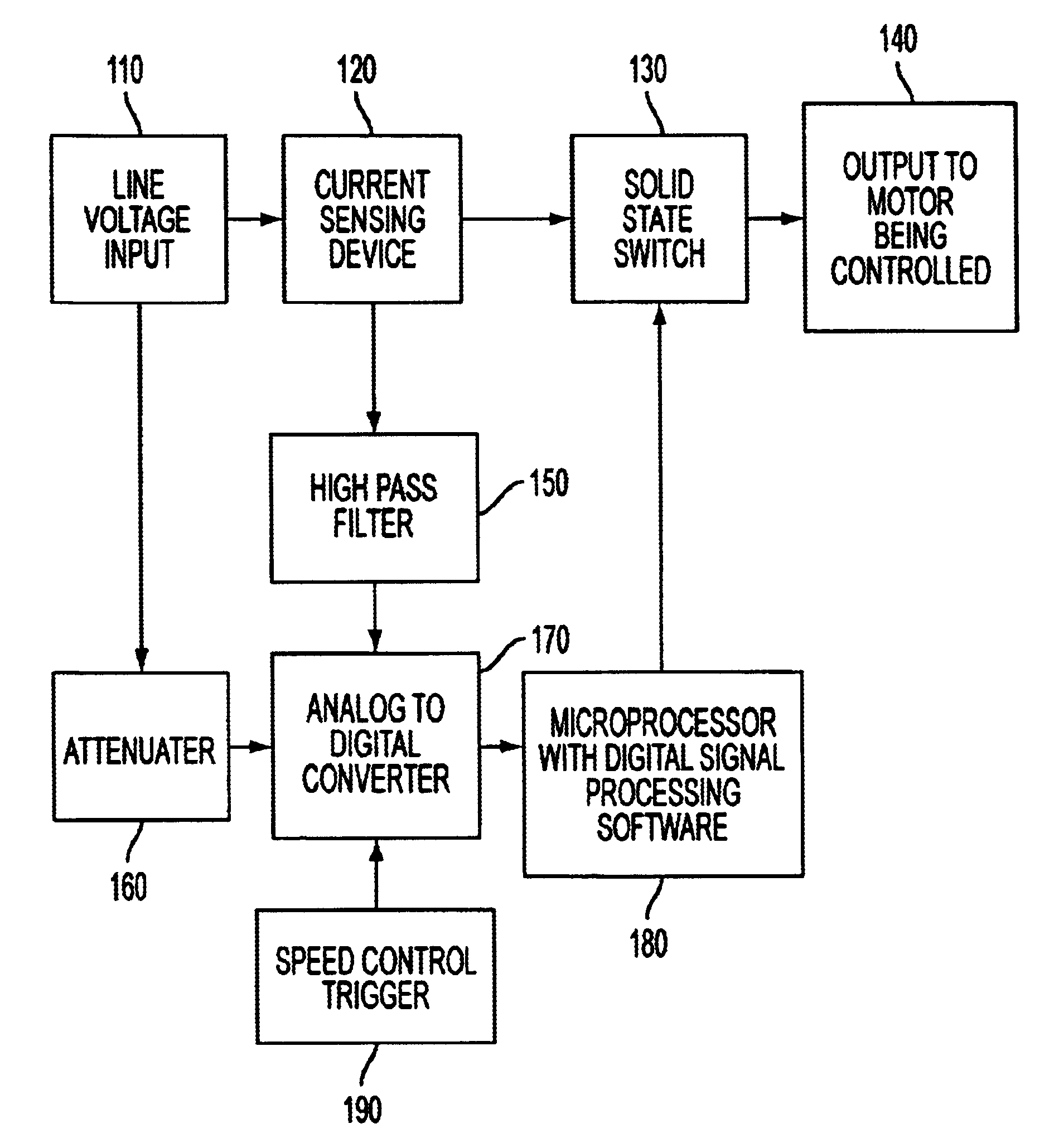
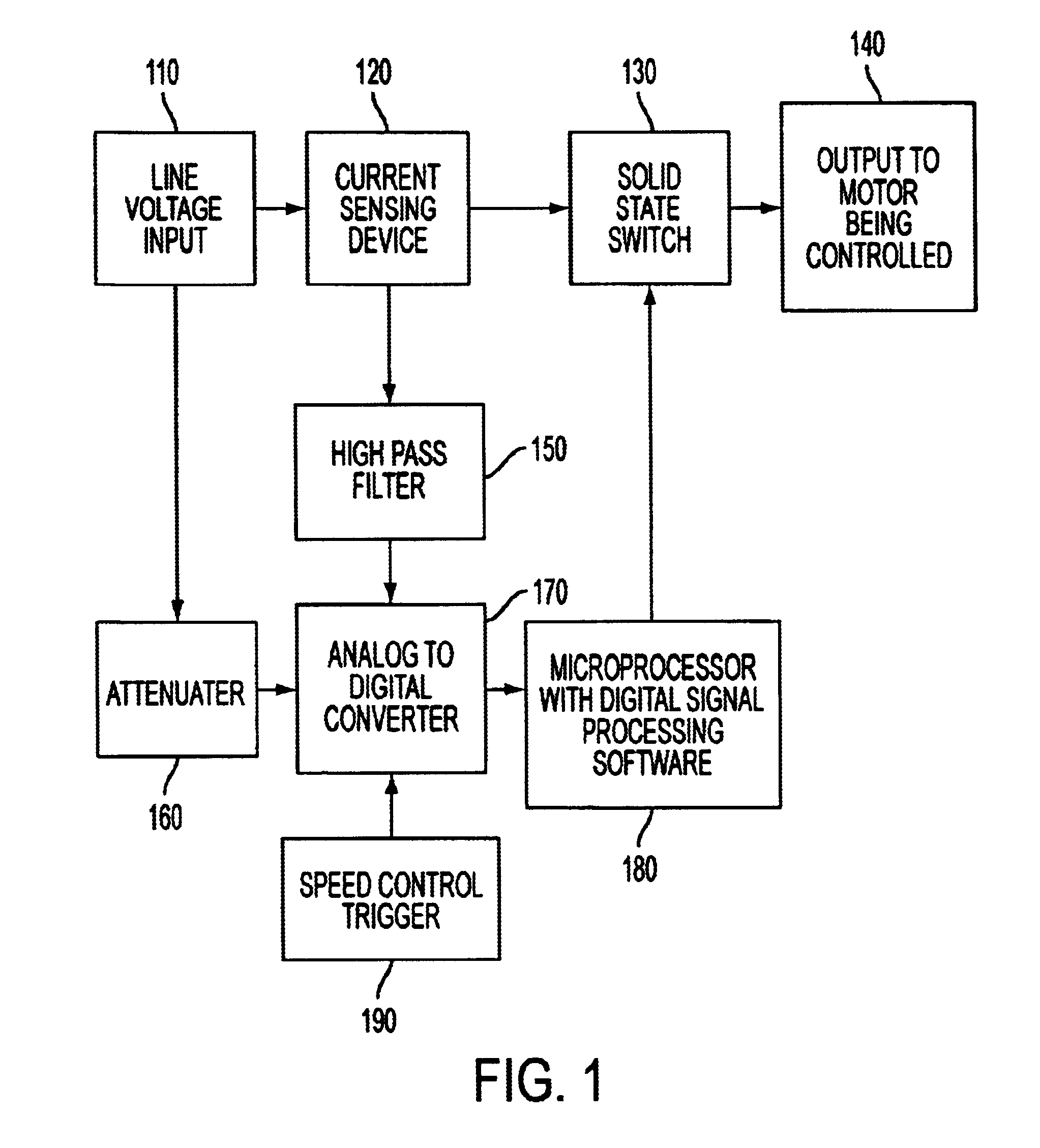
The context of the invention can include a speed control for an electric motor possessing a commutator and brushes.

This motor speed control device senses the speed of an electric motor by means of digital signal processing the armature current waveform. The device is applicable to AC and DC motors possessing a commutator and brushes. The motor armature current waveform contains spikes or fast rise-time trans...


PUM


Abstract

Systems and methods are described for improving the performance of electric motors which employ commutators and brushes. A method includes improving the performance of an electric motor that employs a commutator and brushes comprising: sending power to the motor, reading a set of data from the motor using an analog to digital converter and a microcontroller configured to execute digital signal processing software, setting a speed for the motor, and maintaining the speed for the motor based on the set of data as analyzed by the microcontroller. An apparatus includes a current sensing device coupled in series to the motor to monitor the current of the motor, a solid state switch coupled through the microcontroller to the current sensing device which controls the amount of current delivered to the motor, a high pass filter coupled to the current sensing device that removes the 60 Hz frequency component from the voltage of the current sensing device, an analog to digital converter that sends digital output to the microcontroller, and a microcontroller to perform digital signal processing coupled to the solid state switch.

Description

1. Field of the InventionThe invention relates generally to the field of electric motors. More particularly, the invention relates to electric motors which employ commutators and brushes. Even more particularly, the invention relates to techniques for controlling and maintaining the speed of electric motors that employ commutators and brushes.2. Discussion of the Related ArtElectric motors have been the major source of power for many different types of equipment since their early days. The power source can be either AC or DC. AC and DC performance differ in that the DC power source has both higher efficiency and output.An electromagnet is the basis of an electric motor. The armature in the motor is an electromagnet made by coiling thin wire around two or more poles of a metal core. The armature has an axle, and the commutator is attached to the axle. The commutator is typically a pair of plates, which provide the two connections for the coil of the electromagnet, attached to the axl...

Claims


Application Information

Patent Timeline
Patent Type & Authority Patents(United States)
IPC IPC(8): H02P25/14H02P23/14H02P25/02
CPCH02P7/0094H02P23/14H02P25/14
Inventor MARUSARZ, RONALD K.
Owner SOUTHERN ILLINOIS UNIVERSITY
Why Eureka
Try Eureka