High frequency and multi frequency band ultrasound transducers based on ceramic films

a multi-frequency band, ultrasound transducer technology, applied in the field of high frequency and multi-frequency band ultrasound transducers based on ceramic films, can solve the problems of brittle plate, limited self-supporting plate thickness, difficult and expensive problems

Inactive Publication Date: 2004-07-13
PREXION
View PDF7 Cites 60 Cited by
  • Summary
  • Abstract
  • Description
  • Claims
  • Application Information

AI Technical Summary

Benefits of technology

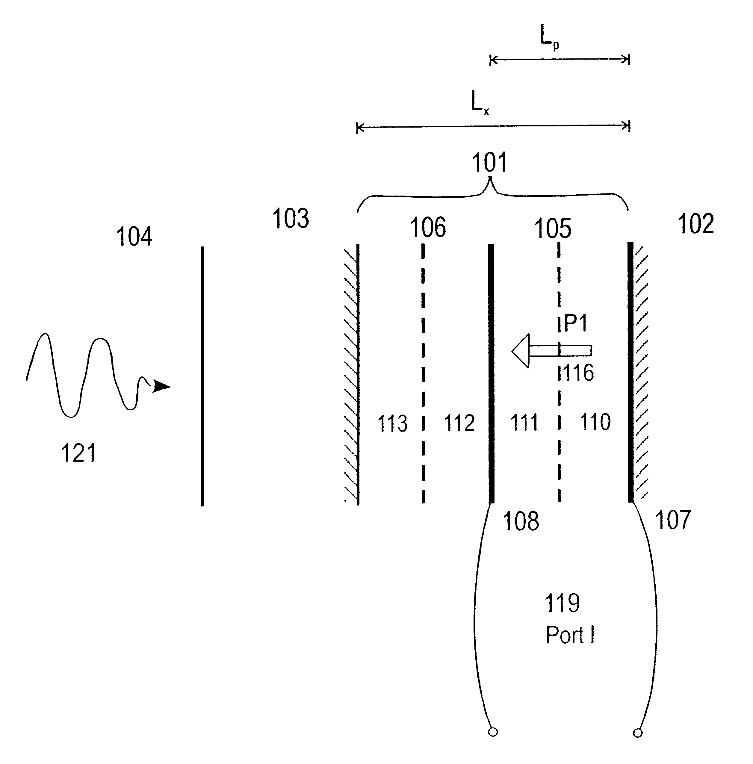
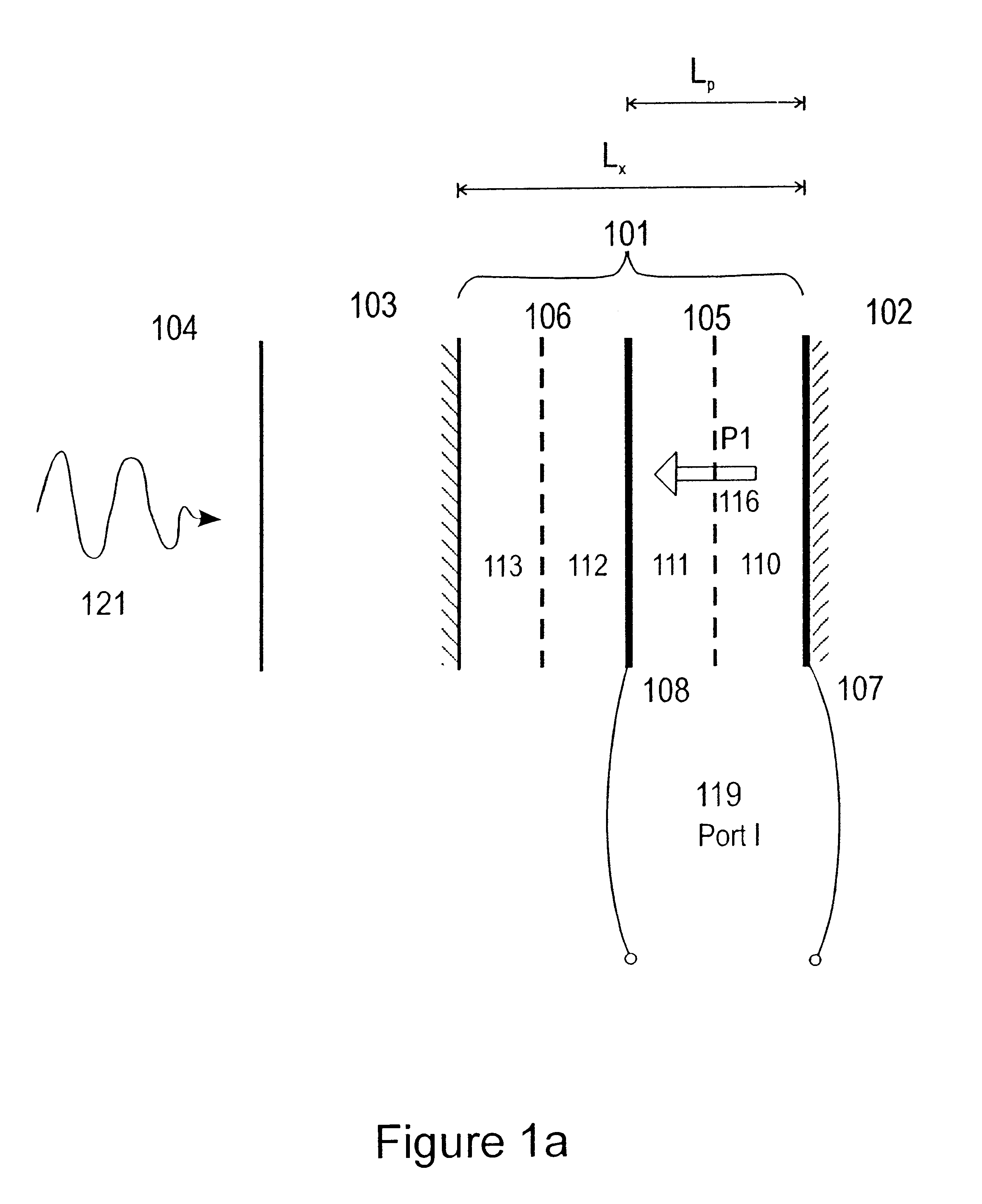
The close to constant characteristic impedance within the transducer plate implies that the mechanical thickness resonances of the transducer are determined by the total plate thickness, not by the thicknesses of the individual film layers that composes the plate. By placing electrodes inside the transducer plate, the transducer plate can operate over a larger range of resonances, from .lambda. / 2 to multiple .lambda. resonances, while the electrodes at the center frequency are placed at antinodes with distance .about..lambda. / 2 internal in the transducer plate, maximizing the electromechanical coupling of the electrodes over the actual frequency band. This allows the use of thicker transducer plates than the standard .lambda. / 2 transducer plates, which provides manufacturing advantages as described below.
The multi layer structure can be made with tape casting of the films, or deposition onto a substrate with thick film printing, sol-gel deposition, or other deposition techniques. With tape-casting techniques one can typically make films with thickness in the range of .about.10-30 .mu.m. The raw films before sintering are quite pliable, and layers of films can be stacked to form plates of larger thickness. The films are sintered at temperatures .about.1000.degree. C., which makes the plate brittle and limits the lower thickness of self-supporting plates and hence the highest operable frequency with ordinary .lambda. / 2 resonant transducer plates made with tape casting techniques. By placing electrodes inside the plate as described, one can obtain efficient electro-acoustic coupling at frequencies where the total plate thickness L.sub.x is substantially larger than .lambda. / 2, allowing increased thicknesses L.sub.x of the total transducer plate that increases the stability during the sintering process and other handling of the plate. The design is specially useful for operating frequencies above .about.30 MHz.
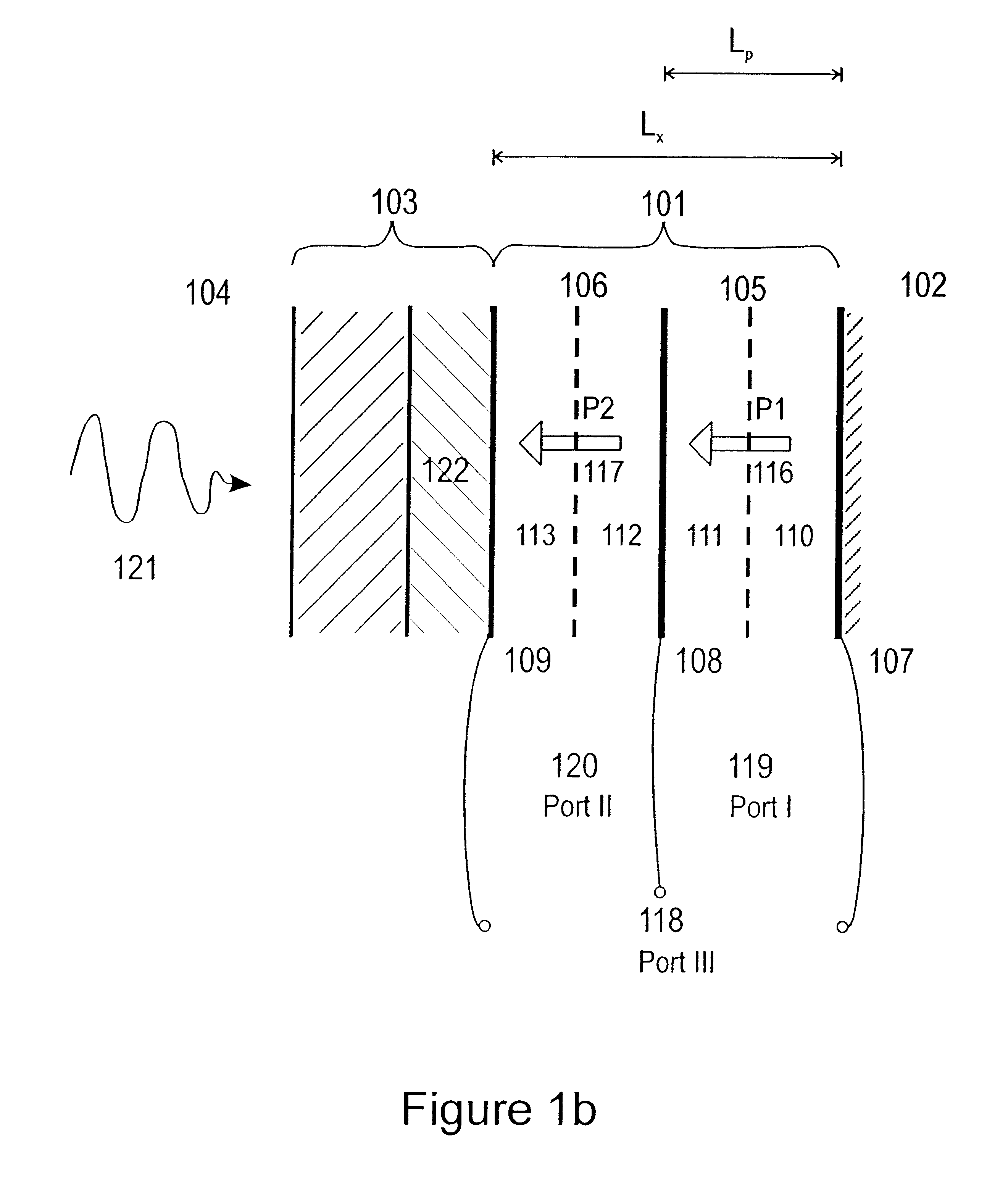
By introducing more electrodes both at the front face of the transducer plate and between film layers inside the composite plate, one obtains multiple electric ports that can be efficient in different frequency bands. Electrodes at both faces of the transducer plate for example, can be used as a lower frequency electric port that is efficient around lower resonance frequencies of the plate, for example .lambda..sub.0 / 2 resonance at f.sub.0 =c.sub.1 / 2L.sub.x for the low characteristic impedance backing. According to the invention, the signals from several electric ports can be combined for improved transmit and receive characteristics, either through direct galvanic connection of electrodes, or in transmit mode through special drive signals on the electrodes, or in receive mode through a combination of the signals from electric ports after isolation amplifiers.

Problems solved by technology

Today, lapping of the ceramic plate is the common technology to manufacture plates with correct thickness, which becomes difficult and expensive at thicknesses in ranges below 50-60 .mu.m, corresponding to frequencies above 30-40 MHz.
The films are sintered at temperatures .about.1000.degree. C., which makes the plate brittle and limits the lower thickness of self-supporting plates and hence the highest operable frequency with ordinary .lambda. / 2 resonant transducer plates made with tape casting techniques.
With deposition of the ceramic films onto a substrate, one has a problem that many actual substrate materials contaminate the ferroelectric ceramic film during the sintering processes, so that in the neighborhood of the substrate, the film loses its ferroelectric properties, and hence also its piezoelectric properties.
Manufacturing of load matching layers with correct thickness and characteristic impedance at these high frequencies (i.e. thin layers) presents problems.

Method used


Image

  • High frequency and multi frequency band ultrasound transducers based on ceramic films
  • High frequency and multi frequency band ultrasound transducers based on ceramic films
  • High frequency and multi frequency band ultrasound transducers based on ceramic films

Examples


Embodiment Construction

Typical embodiments according to the invention are shown in FIGS. 1a-1c, where all Figures. show a composite transducer plate 101 made of several layers of ferroelectric, ceramic films and possibly films of other material with characteristic impedance close to that of the ceramic films. In FIGS. 1a and 1b it is shown for sake of example 4 layers 110-113 of films, while in FIG. 1c it is shown 6 layers 110-115. The composite plate with characteristic impedance Z.sub.x is mounted on a backing material 102 with characteristics impedance Z.sub.B. The backing material absorbs waves so that waves reflected from the back side of the backing can be neglected. The backing material hence appears to have infinite thickness. Back impedance matching layers can possibly be mounted between the composite ceramic plate and the backing, to improve sensitivity in selected frequency bands according to known principles. The resonant nature of such matching limits the total bandwidth, and in the following...


PUM


Abstract

A design and a manufacturing method of ultrasound transducers based on films of ferro-electric ceramic material is presented, the transducers being particularly useful for operating at frequencies above 10 MHz. The designs also involve acoustic load matching layers that provides particularly wide bandwidth of the transducers, and also multiple electric port transducers using multiple piezoelectric layers, for multi-band operation of the transducers over an even wider band of frequencies that covers ~4 harmonics of a fundamental band. A transceiver drive system for the multi-port transducers that provides simple selection of the frequency bands of transmitted pulses as well as transmission of multi-band pulses, and reception of scattered signals in multiple frequency bands, is presented. The basic designs can be used for elements in a transducer array, that provides all the features of the single element transducer for array steering of the focus and possibly also direction of a pulsed ultrasound beam at high frequencies and multi-band frequencies. The manufacturing technique can involve tape-casting of the ceramic films, deposition of the ceramic films onto a substrate with thick film printing, sol-gel, or other deposition techniques, where manufacturing methods for load matching layers and composite ceramic layers are described.

Description

1. Field of the InventionThe present invention is directed to technology and design of efficient ultrasound transducers for high frequencies, and also transducers with multiple electric ports for efficient operation in multiple frequency bands, for example frequency bands with a harmonic relation. The invention has special advantages where the highest frequencies are above 10 MHz, but has also applications for transducers at lower frequencies.2. Description of the Related ArtMedical ultrasound imaging at frequencies above .about.10 MHz, has a wide range of applications for studying microstructures in soft tissues, such as the composition of small tumors or a vessel wall. In many of these situations it is also desirable to use ultrasound pulses with frequencies in several frequency bands, for example to1. use a pulse with frequencies in a low frequency band of for example 30-40 MHz to get larger image depth for an overview image, and then be able to switch to or use simultaneously a ...

Claims


Application Information

Patent Timeline
Patent Type & Authority Patents(United States)
IPC IPC(8): B06B1/06
CPCB06B1/0688
Inventor ANGELSEN, BJORN A. J.JOHANSEN, TONNI F.O SLASHED.STG.ANG.RD, JARLE
Owner PREXION
Why Eureka
Try Eureka