Stent (or stent graft) locating device

a locating device and stent technology, applied in the field of stent or stent graft locating device, can solve the problems of no prognosis, increased likelihood of multiple organ failure, brain disorders,

Inactive Publication Date: 2004-07-20
ISHIMARU SHIN
View PDF29 Cites 215 Cited by
  • Summary
  • Abstract
  • Description
  • Claims
  • Application Information

AI Technical Summary

Benefits of technology

FIG. 9 is an enlarged view depicting a state in which lead-in wires are engaged with t...

Problems solved by technology

An aneurysm which grows due to hardening or inflammation of an artery, when left untreated expands gradually and fatally ruptures creating a disease condition that has no prognosis.
However, this type of disease condition is often experienced by old which increases the likelihood of multiple organ failure such as disorders of the brain, heart the kidneys, etc.
In addition, the surgical operation is often excessively invasion.
Thus, a surgical operation for this disease condition that is limited to safe technique which can avoid the danger of these difficulties is desired.
However, conventional stents and stent grafts cannot be contracted again after they have been discharged from a catheter to expand and located in a blood vessel.
Therefore, when a disorder of the blood stream and internal organ happen because of erroneous positioning of...

Method used


Image

  • Stent (or stent graft) locating device
  • Stent (or stent graft) locating device
  • Stent (or stent graft) locating device

Examples


embodiment

Referring to the drawings, an embodiment of the invention will be explained below.

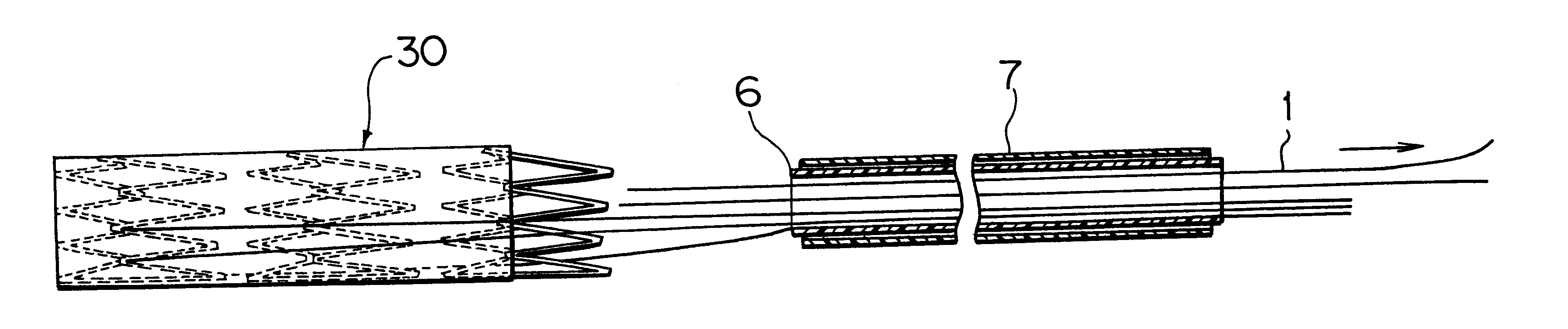
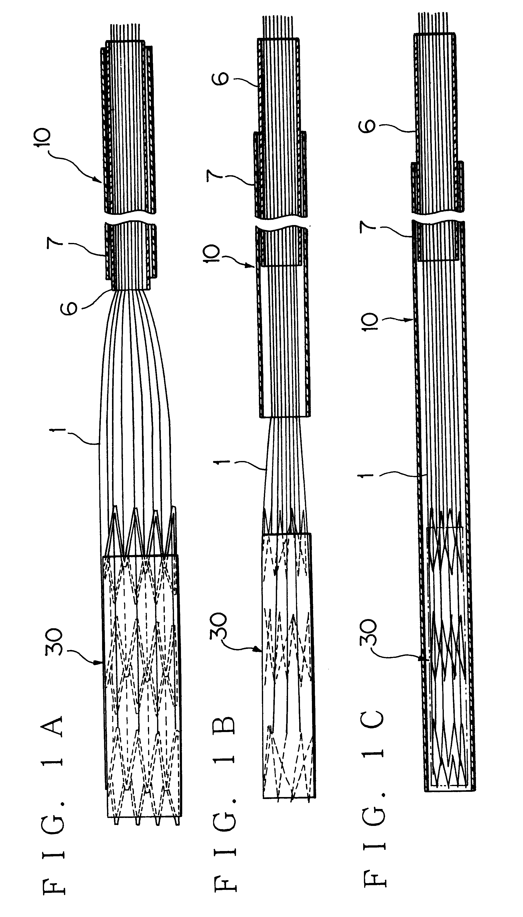
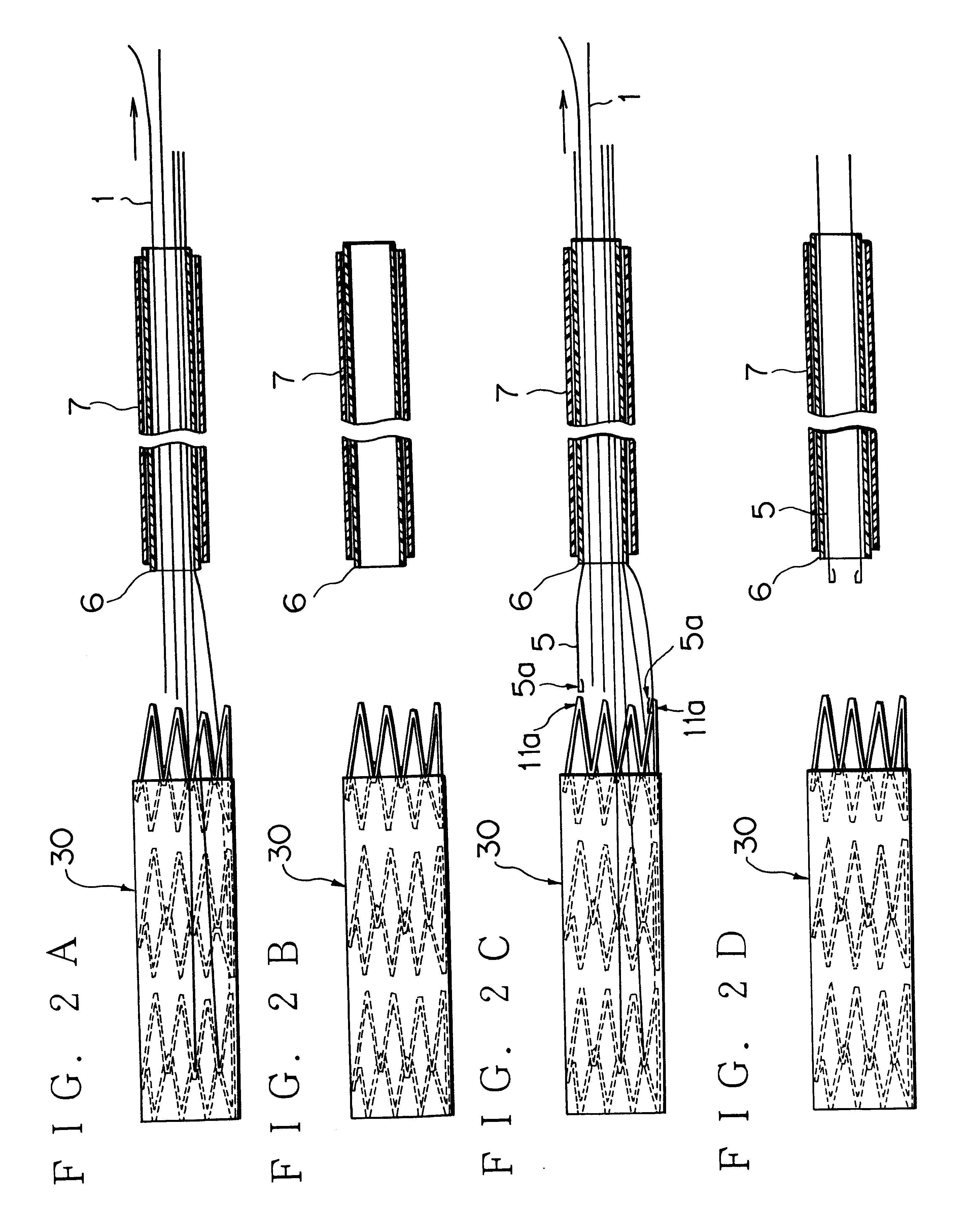
As seen from FIG. 6, a stent 20 is composed of three elastic rings 11 each made of a metallic wire of a shape memory alloy (NiTi) and formed in a spring shape, which are coupled by means of coupling wires 12 each made of the metallic wire by welding or soldering. The stent 20 is sewn into a graft (artificial blood vessel) 13 of Teflon (PTFE) as shown in FIG. 7 to form a stent graft 30. On the other hand, the guiding wire (not shown) is previously inserted from the incised portion of a peripheral artery such as a femoral artery in a thoracic aortic aneurysm model to reach the incised portion of the brachial artery through the diseased part of the blood vessel. The guiding wire derived from the incised portion of the femoral artery is passed into the hollow portion of the stent graft 30 and into the guiding wire channel 6b (6C) (FIGS. 4A and 4B) of the pushing rod 6 in the stent graft locating device 10 ...


PUM


Abstract

A stent locating device that includes leading wires, a pushing rod for holding the leading wires, and a sheath for loading the pushing rod. The pushing rod includes inner and outer tubes. The inner tube is used as a guiding wire channel. An annular portion between the inner and outer tubes is used as a leading wire channel. The pushing rod may be a single tube having a hollow portion that is used as a guiding wire channel and a plurality of leading wire channels arranged in the body thereof at regular intervals circumferentially. The pushing rod may have a plurality of leading wires, crossing leading wires, or a combination of leading wires and auxiliary leading wires which are distributed at regular intervals circumferentially and are derived from the tip of a leading wire channel(s).

Description

This invention relates to a device for safely locating a stent or stent graft at a diseased site in order to treat a stenotic and expansive disease such as an aneurysm of an artery and other disease conditions.An aneurysm which grows due to hardening or inflammation of an artery, when left untreated expands gradually and fatally ruptures creating a disease condition that has no prognosis. Medicine has little effect on this type of disease condition. Therefore, in order to cure an aneurysm, a surgical operation using an artificial blood vessel, e.g. an operation involving removal of cancer tissue and of replacement by the artificial blood vessel has traditionally been performed. However, this type of disease condition is often experienced by old which increases the likelihood of multiple organ failure such as disorders of the brain, heart the kidneys, etc. In addition, the surgical operation is often excessively invasion. Thus, a surgical operation for this disease condition that is ...

Claims


Application Information

Patent Timeline
IPC IPC(8): A61F2/06A61F2/07A61F2/82A61F2/89A61F2/91A61F2/95
CPCA61F2/07A61F2/95A61F2/89A61F2/91A61F2002/075A61F2002/825A61F2002/9505A61F2002/9511A61F2220/0041A61F2220/0058A61F2220/0075A61F2002/9665
Inventor ISHIMARU, SHIN
Owner ISHIMARU SHIN
Why Eureka
Try Eureka