
Cyclic solvent process for in-situ bitumen and heavy oil production

a solvent and in-situ technology, applied in drinking water installations, borehole/well accessories, cabinets, etc., can solve the problems of insufficient solvent distribution, high solvent cost, and inability to achieve effective solvent distribution in bitumen reservoirs

Inactive Publication Date: 2004-08-03
EXXONMOBIL UPSTREAM RES CO
View PDF103 Cites 120 Cited by
  • Summary
  • Abstract
  • Description
  • Claims
  • Application Information

AI Technical Summary

Benefits of technology

The invention is a process for extracting bitumen from oil sand and heavy oil reservoirs using a solvent-based process. The process involves injecting a viscosity reducing solvent into the reservoir at a pressure above the liquid / vapor phase change pressure of the solvent. This pressure should be high enough to cause geomechanical formation dilation or pore fluid compression. The solvent should then mix with the bitumen under these conditions and reduce the pressure in the reservoir to below the liquid / vapor phase change pressure of the solvent. The process can be repeated as required. The invention has advantages in maximizing solubilization and production rates.

Problems solved by technology

The disadvantages are: high solvent cost and inherently low production rate limited by mass transfer of the solvent into the bitumen.
A problem that remains outstanding is to maximize extraction bitumen from oil sand and heavy oil reservoirs with maximum economy, minimum loss of solvent and to leave minimal residual bitumen in the oil sand and heavy oil reservoirs.
A problem unaddressed to date is that of effective solvent distribution in a bitumen reservoir.
If the solvent distributes too quickly throughout the reservoir there is a tendency for the solvent to be distributed along long thin solvent fingers penetrating into the reservoir from the point of injection.
This leads to ineffective viscosity reduction and poor and difficult recovery of bitumen.
If the solvent is insufficiently distributed in short thick fingers then solvent-bitumen contact is too limited to provide efficient bitumen extraction.
The injection and production procedures are repeated until the produced solvent to oil ratio (PSOR) is so high that the incremental production becomes uneconomical.
If the solvent is distributed too widely during injection, there will be insufficient viscosity reduction to yield economic production rates.
In this case, the solvent finger, being thin, would resaturate rapidly along its length during production, trapping a large fraction of the solvent away from the wellbore and behaving like uncontrolled hydraulic fracturing.
The accompanying high solvent gas production was detrimental to oil production.
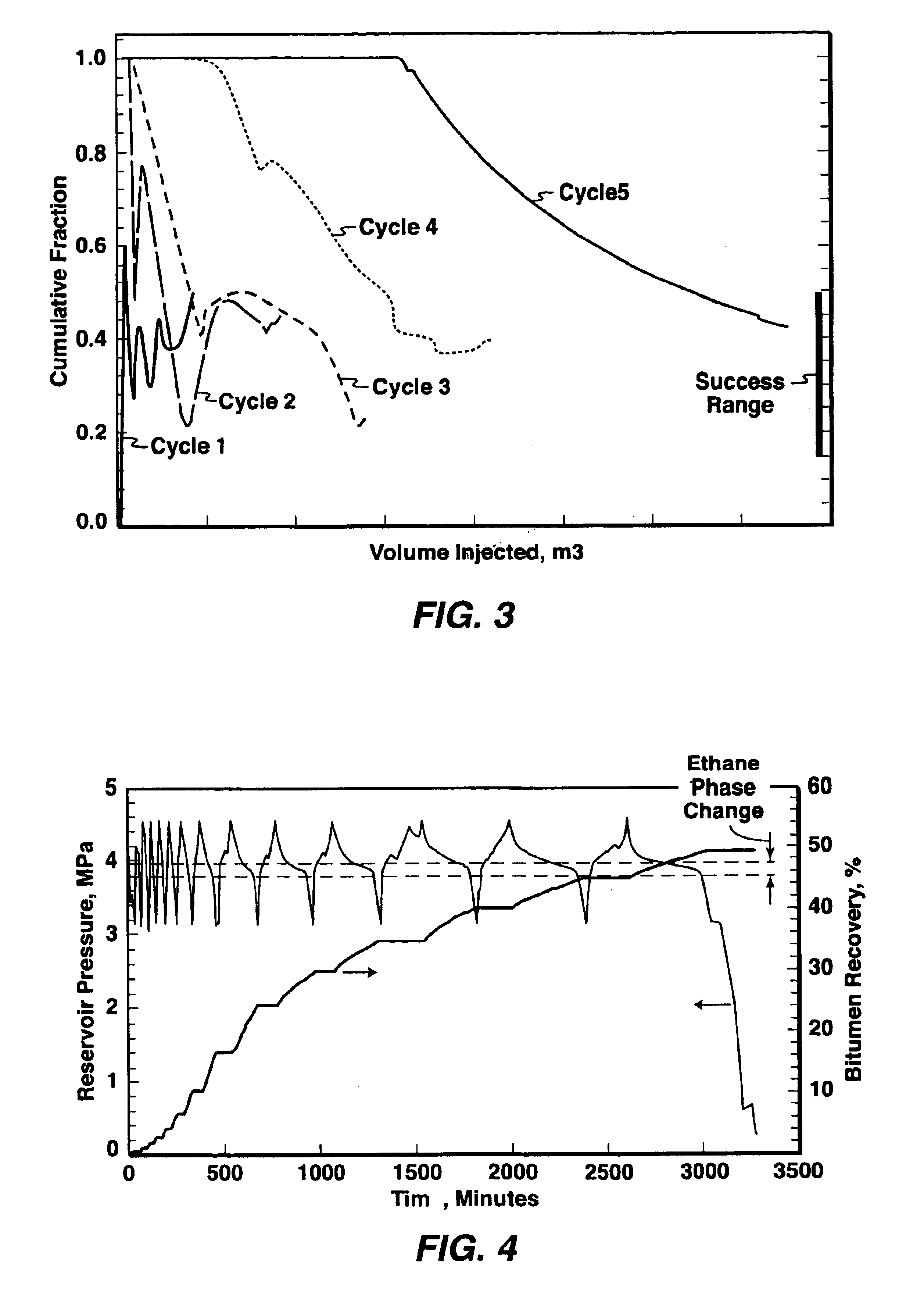
High PSOR in late cycles implies low effectiveness of the injected solvent for oil mobilization.
High vent gas production can often lead to "gas coning" effect, and high PSOR and is detrimental to crude oil production.
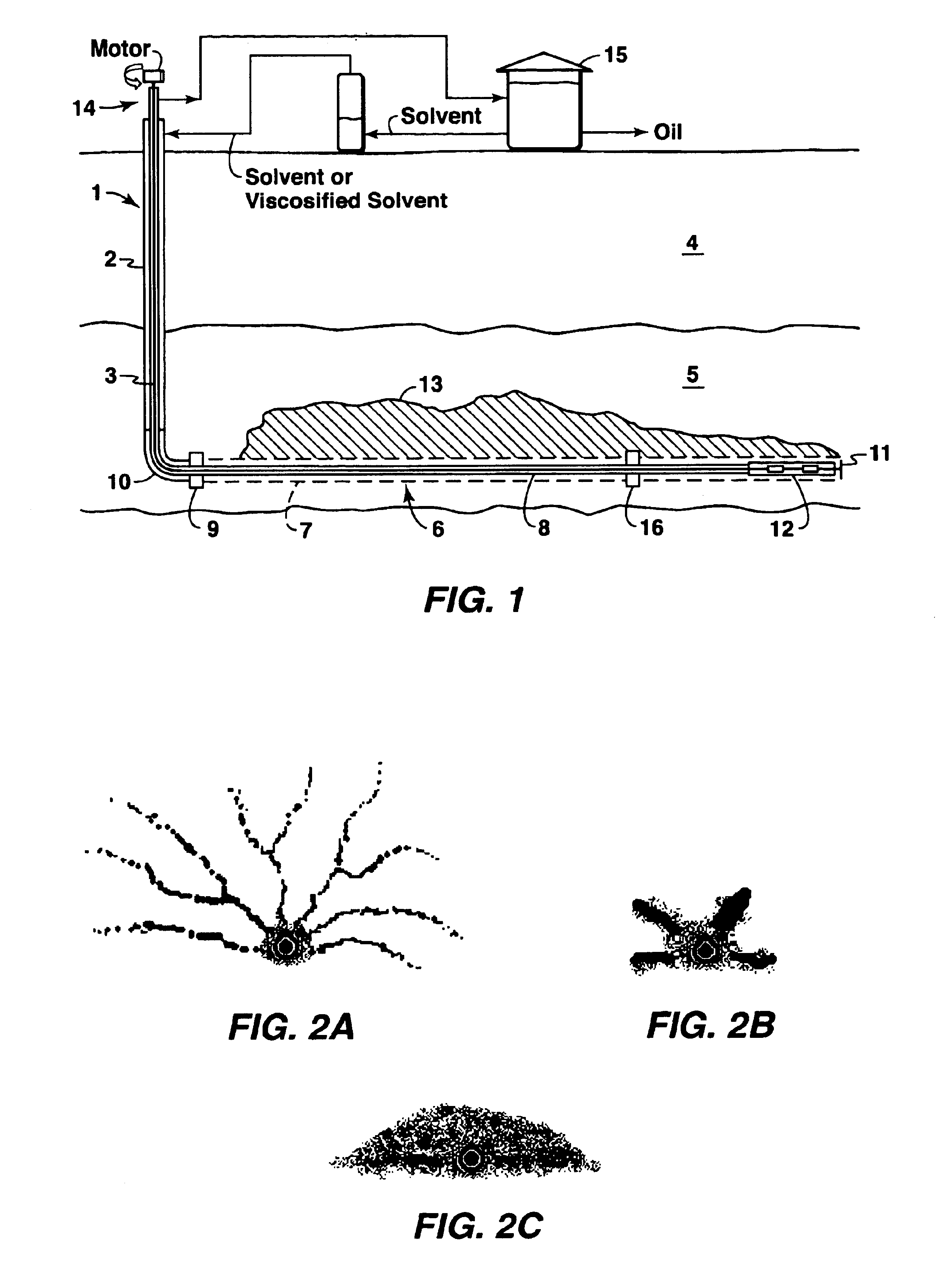
If the ethane injected was sparsely distributed by thin long fingers, the total bitumen produced would be small and ethane recovery would be very poor (2A).
These solvents, though not readily miscible with bitumen initially, would become miscible after multiple contact with bitumen in the reservoir.
For a solvent-based process with pure ethane injection, production pressure drawdown may be limited by the ethane's saturation pressure.
This reduces the effectiveness of gas in mobilizing oil during low-pressure production.
Lifting efficiency is significantly improved as a result of the down-hole gas separation since gas is known to impede pump efficiency.
The hydrates, however, have a tendency to form in tubings or flowlines when gas expansion reduces fluids to sufficiently low temperatures.
These hydrates blocked the tubing and affected production.

Method used


Image

  • Cyclic solvent process for in-situ bitumen and heavy oil production
  • Cyclic solvent process for in-situ bitumen and heavy oil production
  • Cyclic solvent process for in-situ bitumen and heavy oil production

Examples


Embodiment Construction

Commercial Scale Application of Cyclic Solvent Process

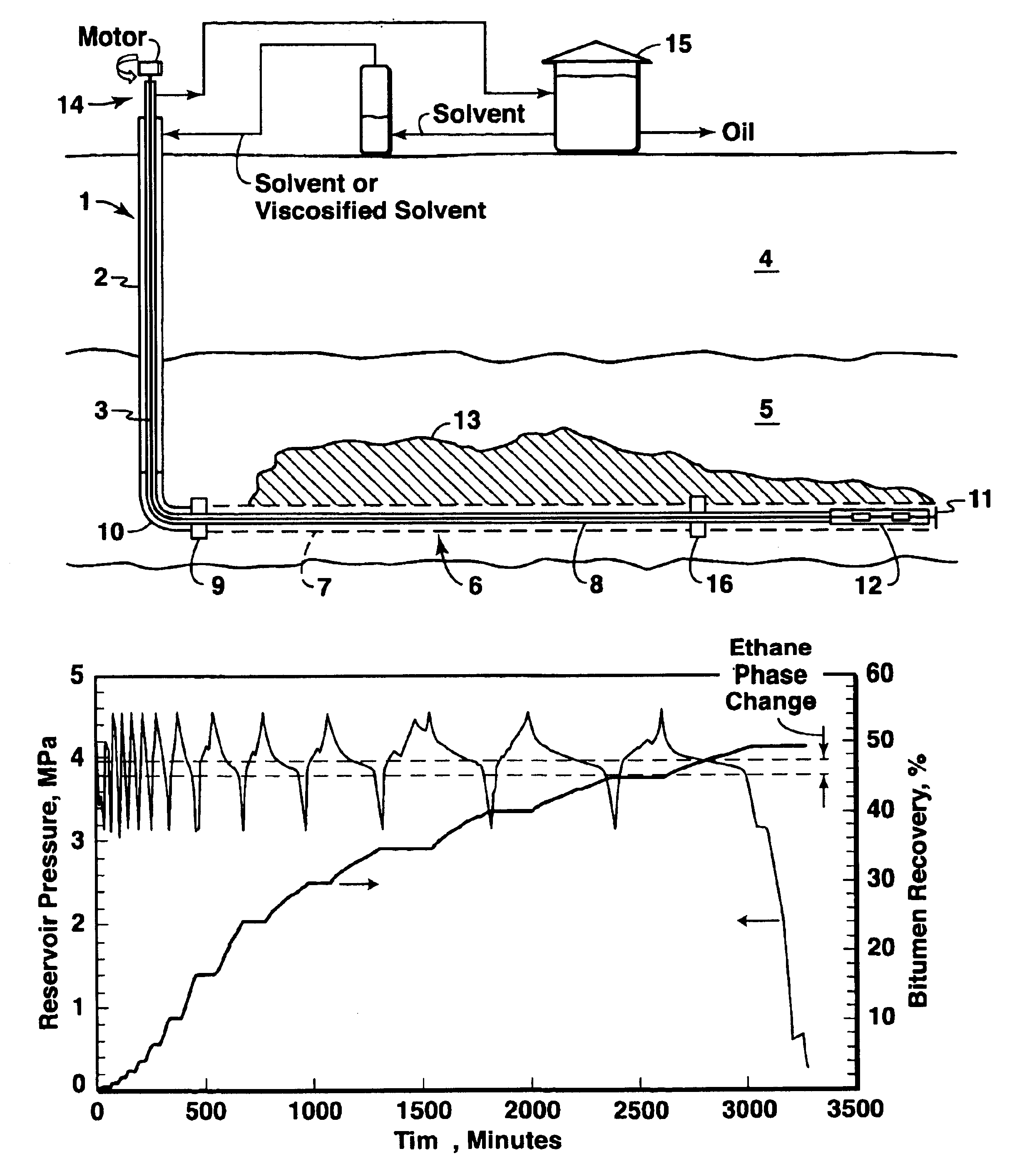
An example of how the process can be applied to produce Cold Lake bitumen on a commercial scale is described below. Field scale prediction from the simulation indicates that a commercial well of 750 m long can produce approximately 50 m3 / d of bitumen on the average from a Cold Lake thin reservoir. Sixty such wells (see FIG. 1) on production operations would be required for a continuous bitumen production of 3,000 m3 / d at a central plant. Each well would operate 9 years and recover about 25-30% of the bitumen in place. New wells would have to be drilled and started up to replace those that are approaching the end of the well life.

To reduce cost and environmental impact, ten wells are drilled from the same surface pad location. The horizontal sections of the 5 wells are oriented in parallel in the same direction in the reservoir while the other five wells are oriented in the opposite direction. Spacing of the wells in parallel in t...


PUM

PropertyMeasurementUnit
boiling pointaaaaaaaaaa

Abstract

A process for recovery of hydrocarbons in a production fluid from an underground reservoir of said hydrocarbons, the process comprising of: (a) injecting a viscosity reducing solvent of a fraction of said hydrocarbons into said reservoir at a pressure in the reservoir of above a liquid / vapor phase change pressure of a fraction of said solvent; said pressure in said reservoir also being sufficient to cause geomechanical formation dilation or pore fluid compression, and then, (b) allowing said solvent to mix with said hydrocarbons under pore dilation conditions, and then, (c) reducing the pressure in said reservoir to below said liquid / vapor phase change pressure of at least said fraction of said solvent thereby evincing solvent gas drive of said fraction of said hydrocarbons from said reservoir; and then, (d) repeating steps (a) to (c) as required.

Description

BACKGROUND TO THE INVENTIONThis invention relates to an in-situ solvent-based process to produce bitumen from oil sand and heavy oil reservoirs.A significant amount of bitumen in Alberta and other parts of the world is located either in thin, bottom water reservoirs or water sensitive sands which are not amenable to exploitation by steam based processes. A potential alternative for extracting these reservoirs is a solvent-based process. The advantages of the solvent-based processes are: little heat loss and limited water handling. The disadvantages are: high solvent cost and inherently low production rate limited by mass transfer of the solvent into the bitumen.In general, many processes and methods utilizing a variety of solvents under a variety of temperature and pressure conditions have been developed to improve solubilization and production of hydrocarbons from reservoirs.Lim et al in Canadian SPE / CIM / Canmet International Conference on Recent Advances in Horizontal Well Applicat...

Claims


Application Information

Patent Timeline
Patent Type & Authority Patents(United States)
IPC IPC(8): C09K8/58C09K8/594
CPCC09K8/58C09K8/594E21B43/16C09K2208/22
Inventor LIM, GIT B.KRY, P. RICHARDLEBEL, J. PIERREKWAN, MORI Y.
Owner EXXONMOBIL UPSTREAM RES CO
Learn More