
Electric arc monitoring systems

a technology of electric arc monitoring and monitoring system, applied in the direction of spectral/fourier analysis, testing electric installations on the transport, instruments, etc., can solve the problems of disaster, fire, and conventional electric arc monitoring, but are of little use in this resp

Inactive Publication Date: 2004-08-03
TELECT
View PDF29 Cites 38 Cited by
  • Summary
  • Abstract
  • Description
  • Claims
  • Application Information

AI Technical Summary

Benefits of technology

It is a related object of embodiments of the invention to permit reliable arc monitoring at distances from electric arcs longer and with less cross-talk or induction than heretofore.
2. the selection of the monitoring frequency band for each purpose is liberated from prior-art constraints and can truly be the result of an optimum tradeoff in sensitivity, speed of detection, prevention or rejection of false signals, desired length of travel and mode of transmission of the arc signature from the arc to the monitoring circuit in different environments.
Accordingly, lower frequency fractals pursuant to embodiments of the invention induce less spurious signals through cross-induction in neighboring circuits than arc signatures having higher frequencies. Low frequency fractals more effectively avoid false alarms from mutual inductance among neighboring circuits than arc signatures at higher frequencies.
In consequence, embodiments of the invention not only permit arc monitoring at considerable distances from the occurrence of arcs in a monitored circuit, but also avoid false alarms in neighboring monitored circuits.

Problems solved by technology

Unfortunately, the same quality of the electric arc or spark that led to electric lighting, electric arc welding and metallurgy, and ignition of internal combustion, has catastrophic effects in electrical faults that cause explosions or devastating fires through chaotic arcing or sparking.
As a result, it became known that the disaster started as a fuel / air explosion in the almost empty center fuel tank.
After theories of sabotage were discounted, the most likely cause turned up as electric sparking or arcing in the fuel system.
Indeed, such kind of sparking or its potential were found on other aircraft which thereupon were grounded for repair.
Conventional electric arc monitoring would, however, appear to be of little use in this respect, inasmuch as it manifestly is too late to recall an aircraft when an arc has sparked an explosion in the fuel system.
Moreover, fuses and circuit breakers are capable of preventing serious overload conditions, but they are generally ineffective to prevent electrical fires and other damage from accidental arcs and sparks which typically generate enough heat for a fire at electric current levels below the level at which the fuse will blow or the circuit breaker will trip.
A major stagnating problem in this respect has been that prior-art development has run its course in its fear of false alarms.
Of course, false alarms are the bane of alarm systems, as frequent occurrence of false alarms can nullify the utility of any alarm system.
In the A.M. broadcast and above mentioned control and security systems radio frequency band portion of that spectrum, 50 kHz samples can only represent minor fragments of the chaotic arc signature, raising the danger of false alarms from coincidental extraneous signals.
Euclidean geometry suits man-made objects, but cannot realistically express natural configurations.
Problems in this area include false alarms from mutual induction among neighboring monitored circuits.
Such considerations have led to the prior-art conclusion that lowering the frequency of arc signature bands in which arcs are monitored would not effectively reduce cross-induction and false arc alarms therefrom.

Method used


Image

  • Electric arc monitoring systems
  • Electric arc monitoring systems
  • Electric arc monitoring systems

Examples


Embodiment Construction

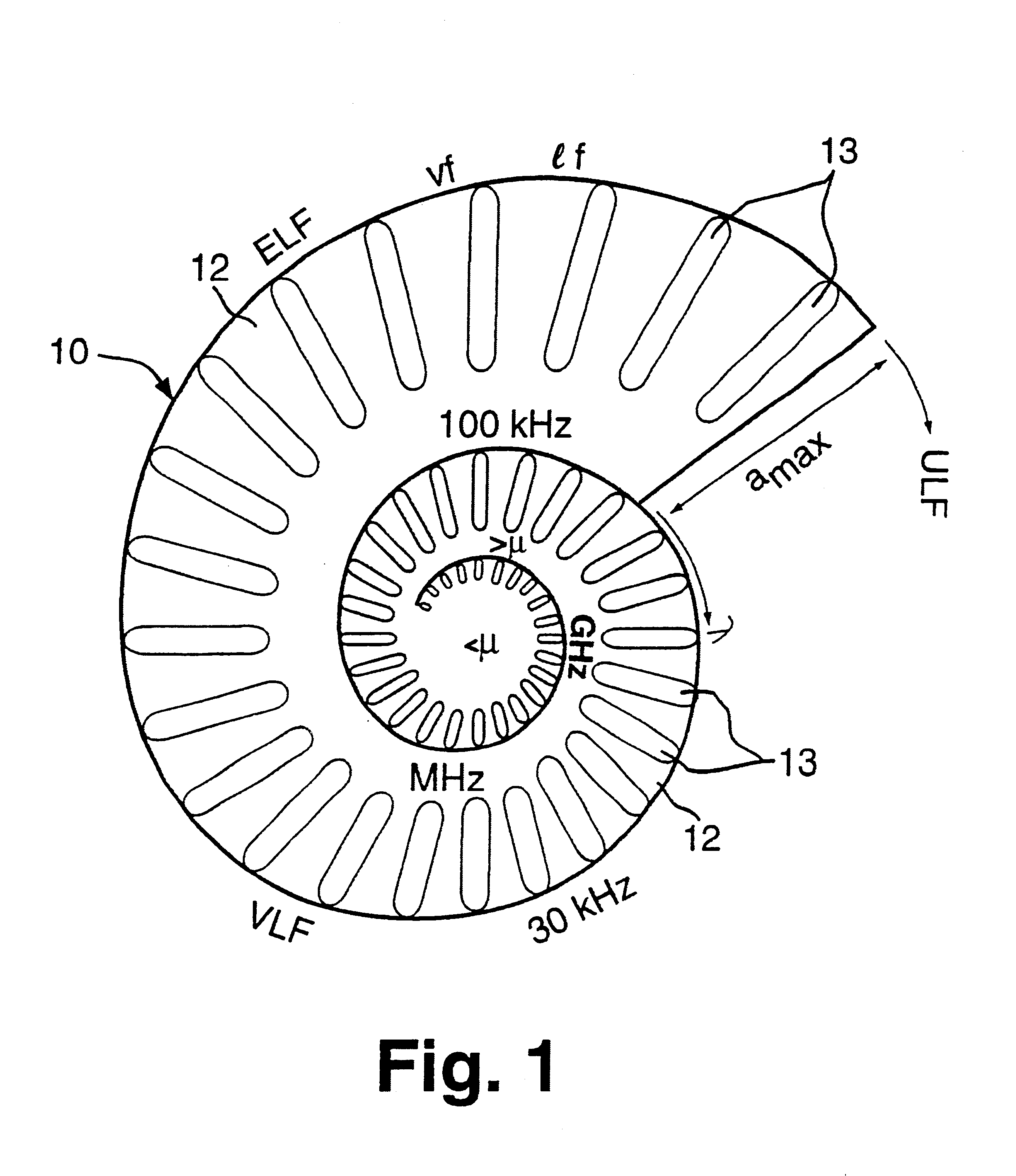
The drawings illustrate some basic modes and also preferred modes of carrying out an aspect of the invention. Since fractal geometry is a visual art as much as a mathematical science, FIG. 1 shows the workings of the invention in terms of a logarithmic spiral. This is a novel aspect, since arc signature spectra traditionally have been plotted in Cartesian coordinates and in terms of frequency. To a large extent, thinking and plotting in terms of frequency was justified, since the frequency of the arc signature is largely independent of the medium through which it travels, while the wavelength of the arc signature depends more directly on the traversed medium.

The traditional focus of the prior art on frequency ab initio obstructed visualization of arc signatures as a logarithmic phenomenon of fractal nature, whereas thinking and plotting in terms of wavelength according to the currently discussed aspect of the invention, leads to visualization, graphic representation and beneficial e...


PUM


Abstract

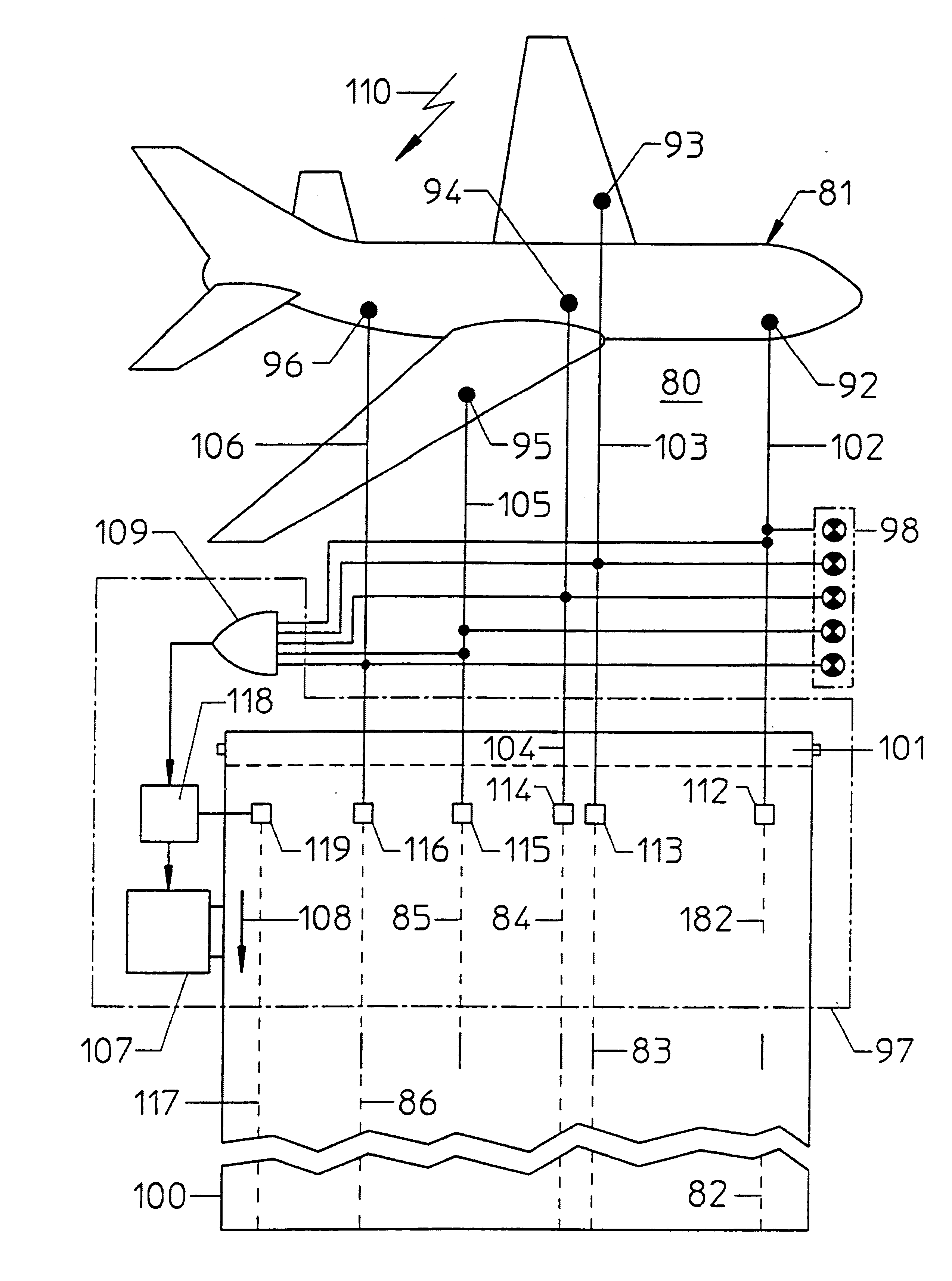
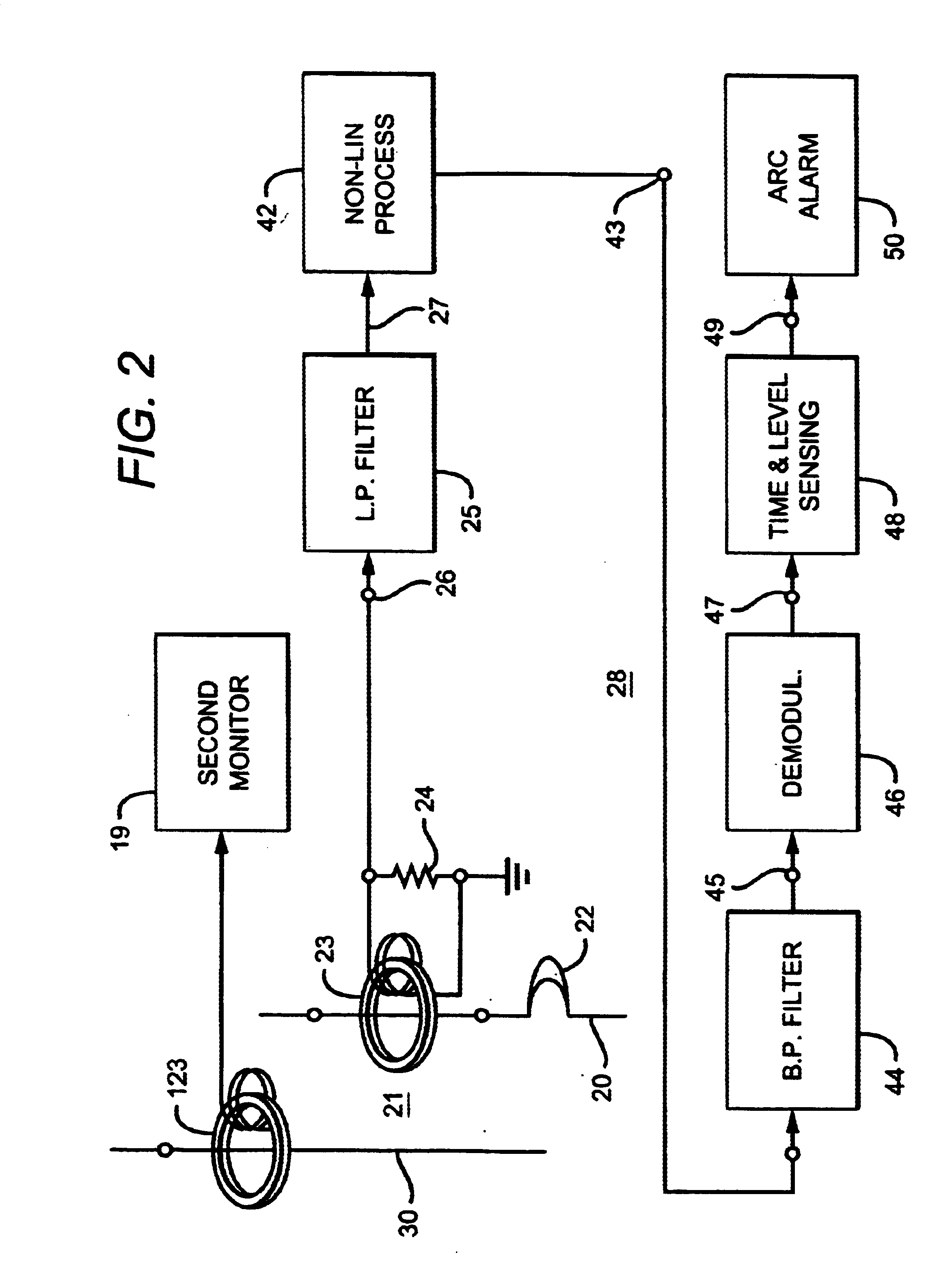
Electric arc monitoring is effected by exploiting the discovery that electric arcs are fractal phenomena in that all essential information that signifies "arc" is contained in each fractal subset. These fractal subsets are logarithmically distributed over the arc spectrum. Monitoring of arcs is most advantageously effected on a fractal subset (16) of low logarithmic order where the amplitude is higher pursuant to the 1 / f characteristic of electric arcs, where cross-induction among neighboring circuit is lower, and where travel between the arc (12) and the arc signature pickup (23) is longer than at the high frequencies customary for electric arc detection. Fractal subset transformation (17) reduces the danger of false alarms. Arc signature portions may be processed in out of phase paths (242, 342) or treated as modulated carriers (42) for monitoring. Aircraft may be equipped with spark monitoring systems (80) that record (82-86) occurence of dangerous sparking at different locations (92-96) aboard the aircraft (81).

Description

The technical field of the invention includes methods and apparatus for monitoring, detecting, indicating, evaluating and signaling electric arcs or sparks.The chaotic electromagnetic emanations manifesting themselves as electric arcs or sparks are closely Linked to matter, wherein electromagnetic interactions bind electrons to nuclei in atoms and molecules and wherein the fundamental unit of electromagnetic radiation is the photon.Indeed, spectra of electric arcs and sparks extend practically from DC through the entire radio-frequency spectrum and through microwave, infrared and light spectra.Useful exploitations of the electric arc and spark phenomenon include the electric arc lamp, electric welding, the electric-arc-type of metallurgical furnace, the arc type of ion generator in satellite thrusters and for propulsion in outer space, the spark-plug-type of ignition in internal combustion engines, and electric spark ignition in gas appliances.Unfortunately, the same quality of the ...

Claims


Application Information

Patent Timeline
Patent Type & Authority Patents(United States)
IPC IPC(8): G01R31/12H02H1/00
CPCG01R31/12H02H1/0015G01R31/008
Inventor PARKER, MICHAEL T.HAM, JR., HOWARD M.HAM, LILLIAN MARGARETKEENAN, JAMES J.BENOIT, LUC P.
Owner TELECT
Learn More