Data transfer control device and electronic equipment

a control device and data transfer technology, applied in the field of data transfer control devices and electronic equipment, can solve the problems of not being able to implement high-speed data transfer overall, the processing capability of the cpu incorporated into the peripheral equipment is lower than the cpu, and the actual transfer speed of the entire system is much slower

Inactive Publication Date: 2004-08-10
SEIKO EPSON CORP
View PDF7 Cites 36 Cited by
  • Summary
  • Abstract
  • Description
  • Claims
  • Application Information

AI Technical Summary

Problems solved by technology

However, some technical problems have been identified with such a data transfer control device conforming to IEEE 1394, as described below.
That is to say, the current IEEE 1394 standard does make it possible to implement transfer speeds up to a maximum of 400 Mbps in practice, however, the presence of processing overheads forces the actual transfer speeds of entire system to be much slower.
In other words, the firmware and application software running on a CPU require large amounts of time for processes such as preparing for transmitting data and reading in received data, which means it is not possible to implement high-speed data transfer overall, no matter how fast the data can be transferred over the IEEE 1394.
A particular problem lies in the fact that a CPU incorporated into peripheral equipment has a lower processing capability than the CPU incorporated into the host system, such as a personal computer.
This makes the problem of processing overheads in the firmware and application software extremely serious.
As a result, it is possible to reduce the processing load on the upper layers, while utilizing limited resources efficiently.

Method used


Image

  • Data transfer control device and electronic equipment
  • Data transfer control device and electronic equipment
  • Data transfer control device and electronic equipment

Examples


Embodiment Construction

Preferred embodiments of this invention are described below with reference to the accompanying drawings.

1. IEEE 1394

The description first relates to an outline of IEEE 1394.

1.1 Data Transfer Speed and Connection Topology

The IEEE 1394 standard (IEEE 1394-1995, P1394-a) enables high-speed data transfer at 100 to 400 Mbps (P1394-b concerns 800 to 3,200 Mbps). It also permits the connection of nodes of different transfer speeds to the same bus.

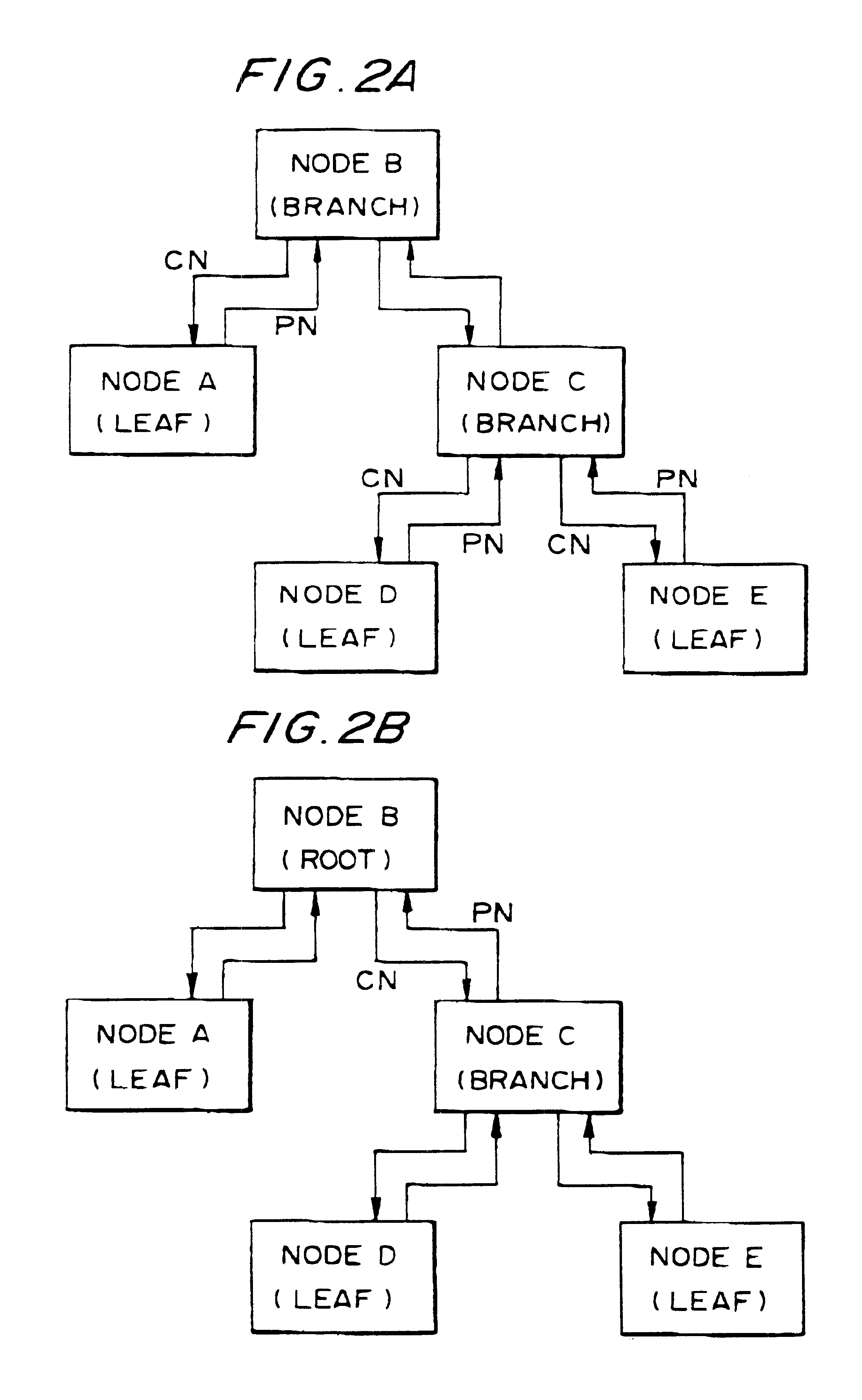
The nodes are connected in a tree configuration in which a maximum of 63 nodes can be connected to one bus. Note that the use of bus bridges enables the connection of approximately 64,000 nodes.

When power is applied or devices have been disconnected or connected, a bus reset occurs and all information relating to connection topology is cleared thereby. After the bus reset, tree identification (determination of the root node) and self identification are performed. Subsequently, the management nodes such as the isochronous resource manager, cycle ma...


PUM


Abstract

The objective is to provide a data transfer control device and electronic equipment that are capable of reducing processing overheads, thus enabling high-speed data transfer within a compact hardware configuration. In addition to a FIFO, an internal RAM capable of storing packets in a randomly accessible manner is provided between a link core and a CPU in a data transfer control device conforming to the IEEE 1394 standard. The RAM storage area is divided into a header area, a data area, and a CPU work area, and the header and data areas are divided into areas for reception and transmission. Tags are used to write the header of a receive packet to the header area and the data thereof to the data area. The data area is divided into areas for isochronous transfer and asynchronous transfer. Pointers are provided for controlling the size of each area in RAM variably, and the size of each area can be varied dynamically after power is switched on. Each area has a ring buffer structure. The size of area storing the header or data of one packet is fixed.

Description

1. Field of the InventionThe present invention relates to a data transfer control device and electronic equipment comprising the same.2. Description of Related ArtAn interface standard called IEEE 1394 has recently been attracting much attention. This IEEE 1394 has standardized high-speed serial bus interfaces that can handle the next generation of multimedia devices. IEEE 1394 makes it possible to handle data that is required to have real-time capabilities, such as moving images. A bus in accordance with IEEE 1394 can be connected not only to peripheral equipment for computers, such as printers, scanners, CD-R drives, and hard disk drives, but also to domestic appliances such as video cameras, VTRs, and TVs. This standard is therefore expected to enable a dramatic acceleration of the digitalization of electronic equipment.The concept of IEEE 1394 is disclosed in various publications, such as "An outline of the IEEE 1394 High Performance Serial Bus" (Interface, April 1996, pages 1 t...

Claims


Application Information

Patent Timeline
Patent Type & Authority Patents(United States)
IPC IPC(8): H04L12/56H04L12/28H04L12/40
CPCH04L49/90H04L49/9031H04L49/9042H04L49/9089H04L12/2803H04L12/2816H04L12/2838
Inventor ISHIDA, TAKUYAOGAWA, TAKAOKAMIHARA, YOSHIYUKI
Owner SEIKO EPSON CORP
Why Eureka
Try Eureka