Stackable ball grid array

Inactive Publication Date: 2004-08-17
MICRON TECH INC
View PDF12 Cites 79 Cited by
  • Summary
  • Abstract
  • Description
  • Claims
  • Application Information

AI Technical Summary

Problems solved by technology

Despite the benefits provided by BGA technology, BGA is still a surface mount technology like FPT and PGA and, thus, is limited by the space available on the mounting surface.
However, regardless of whether FPT, PGA or BGA is implemen

Method used


Image

  • Stackable ball grid array
  • Stackable ball grid array
  • Stackable ball grid array

Examples


Embodiment Construction

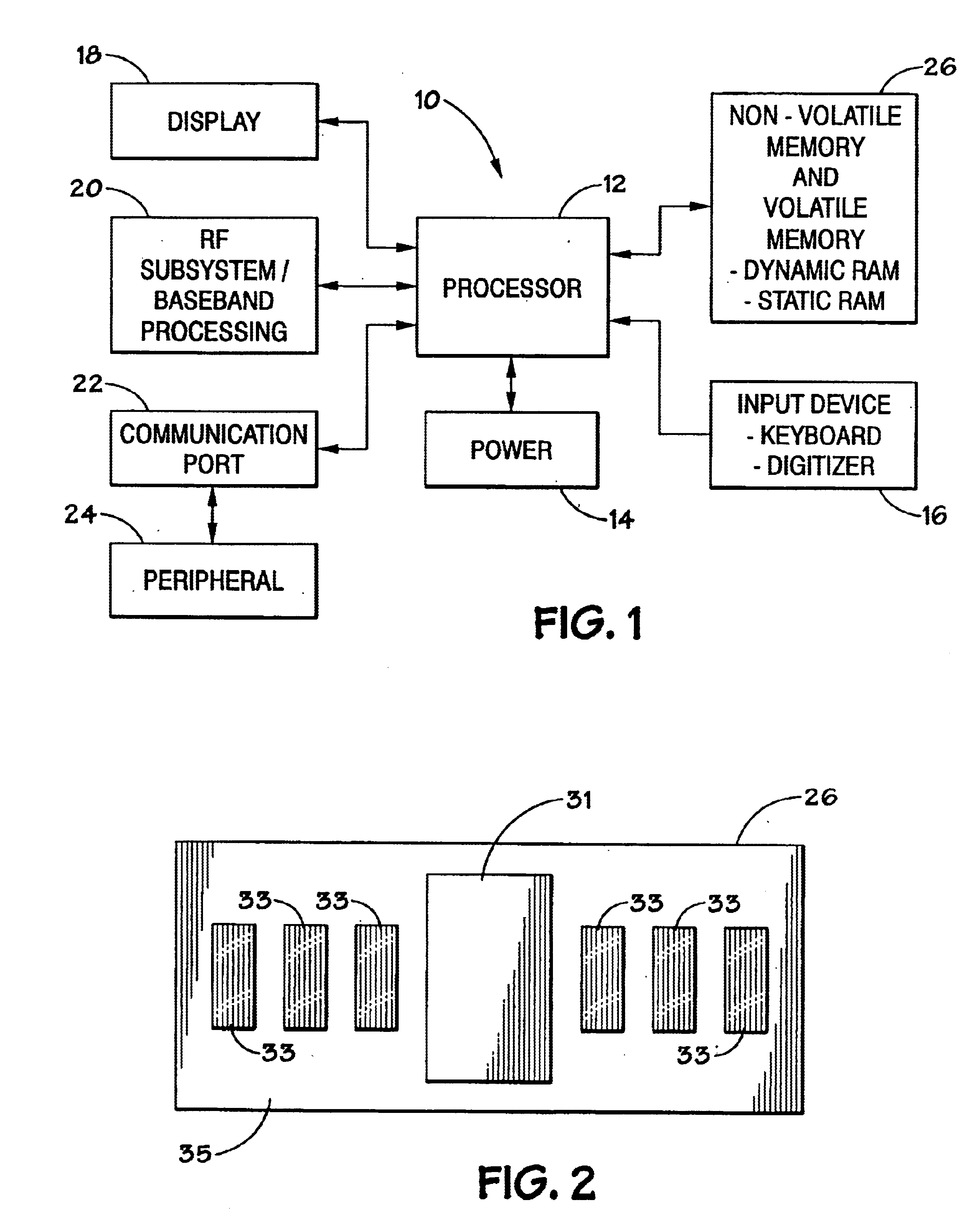
Turning now to the drawings, and referring initially to FIG. 1, a block diagram depicting an exemplary processor-based device generally designated by the reference numeral 10 is illustrated. The device 10 may be any of a variety of different types, such as a computer, pager, cellular telephone, personal organizer, control circuit, etc. In a typical processor-based device, a processor 12, such as a microprocessor, controls many of the functions of the device 10.

The device 10 typically includes a power supply 14. For instance, if the device IO is portable, the power supply 14 would advantageously include permanent batteries, replaceable batteries, and / or rechargeable batteries. The power supply 14 may also include an AC adapter, so the device may be plugged into a wall outlet, for instance. In fact, the power supply 14 may also include a DC adapter, so that the device can be plugged into a vehicle cigarette lighter, for instance.

Various other devices may be coupled to the processor 12...


PUM


Abstract

A stackable package to create a 3-dimensional memory array using ball grid array technology. Specifically, memory chips are coupled to a pre-formed packages which have alignment features to allow for the stacking of the ball grid arrays. The alignment features are used to align and orient each package with respect to an adjacent package, substrate or printed circuit board. The alignment features also support the weight of the adjacent package during solder ball reflow to maintain stack height and parallelism between packages. Each memory device is serially connected to the adjacent memory device through the vias and solder balls on each package.

Description

1. Field of the InventionThe present invention relates generally to electrical circuitry and, more particularly, to a stackable packaging system using ball grid array technology.2. Description of the Related ArtPackaging of electrical circuits is a key element in the technological development of any device containing electrical components. Fine-Pitch Surface Mount Technology (FPT) and Pin Grid Array (PGA) technology are well developed areas of packaging technology. An emerging packaging method has been developed using Ball Grid Array (BGA) technology.BGA technology offers several advantages over FPT and PGA. Among the most often cited advantages of BGA are: reduced co-planarity problems, since there are no leads; reduced placement problems; reduced paste printing problems; reduced handling damage; smaller size; better electrical and thermal performance; better package yield; better board assembly yield; higher interconnect density; multilayer interconnect options; higher I / Os for a ...

Claims


Application Information

Patent Timeline
IPC IPC(8): H01L25/10H01L25/18H05K3/30
CPCH01L25/105H01L25/18H05K3/303H01L2924/15311H01L2924/3011H05K2201/10515H05K2201/10734H05K2203/167H01L2225/1023H01L2225/1058H01L2225/1082H01L2924/0002H01L2924/00H01L23/3128Y02P70/50
Inventor BOLKEN, TODD O.BAERLOCHER, CARY J.COBBLEY, CHAD A.CORISIS, DAVID J.
Owner MICRON TECH INC
Why Eureka
Try Eureka