Method and apparatus for bonding substrate plates together through gap-forming sealer material

a technology of sealing material and substrate plate, which is applied in the direction of manufacturing tools, instruments, other domestic objects, etc., can solve the problems of difficult to control the flexural direction, easy damage, and inability to guarantee the registered position of the bonded substrate pla

Inactive Publication Date: 2004-09-14
HITACHI ELECTRONICS ENG CO LTD
View PDF2 Cites 8 Cited by
  • Summary
  • Abstract
  • Description
  • Claims
  • Application Information

AI Technical Summary

Benefits of technology

It is another object of the present invention to a method and an apparatus which can effectively correct positional deviations which normally inevitably occur to upper and lower substrate plate in the course of hot pressing.
It is still another object of the present invention to provide a method and an apparatus which can obviate the necessity for adjusting compressive properties of cushioning material to be bonded on abutting surfaces of upper and lower pressing members, while guaranteeing to hot-press substrate plates accurately.

Problems solved by technology

However, since the substrate plates of an LCD panel are formed of a relatively fragile material like glass and synthetic resin, they can be easily damaged if hot press members are abutted directly against the respective substrate plates.
However, no matter how strictly substrate plates are one on the other before pressing, it cannot guarantee that the bonded substrate plates stay in the registered position without deviations therefrom.
As a cushioning material is compressed and caused to flex, it is difficult to control the direction of flexure, which more or less differ from one cushioning member to another.
Namely, in some cases the pressing members fail to press substrate plates in a normal straightforward direction, and, since the interposed sealer material is not yet hardened in the hot-pressing stage, may give rise to a detrimental positional deviation between upper and lower substrates.
If the overlapped substrate plates are strongly bonded by an ultraviolet hardening synthetic resin, it will become difficult to determine the gap width precisely later in the hot-pressing stage.
On the other hand, for example, in case upper and lower cushioning members are flexed in the opposite directions upon compression in the hot-pressing stage, this difference in compressive characteristics results in amplification of relative movements of upper and lower substrate plates and thus in augmentation of positional deviations of the upper and lower substrate plates.
However, the pad selection of this sort is very troublesome, in addition to a detrimental drawback that a large amount of material has to be wasted.
Besides, there is little possibility of finding a pair of cushioning pads which perfectly match in compressive characteristics.
Therefore, it is difficult to cope with the demands for fine-pitch LCD panels of higher grades, simply through selection of cushioning pads.
Further, since a pressure is applied on substrate plates under heating conditions, cushioning pads undergo accelerated deteriorations under the influence of heat and need to be replaced after use over a certain period of time.
Thus, there are great limits to preventing positional deviations of substrate plates in a hot-pressing stage by matching compressive characteristics of cushioning pads to be adhered on upper and lower press members.
However, since a pressing method of this sort invariably requires complicate equipments for the supply of a fluid and for the control of fluid pressure, it is still the general practice to resort to a pressing method using cushioning pads.

Method used


Image

  • Method and apparatus for bonding substrate plates together through gap-forming sealer material
  • Method and apparatus for bonding substrate plates together through gap-forming sealer material
  • Method and apparatus for bonding substrate plates together through gap-forming sealer material

Examples


Embodiment Construction

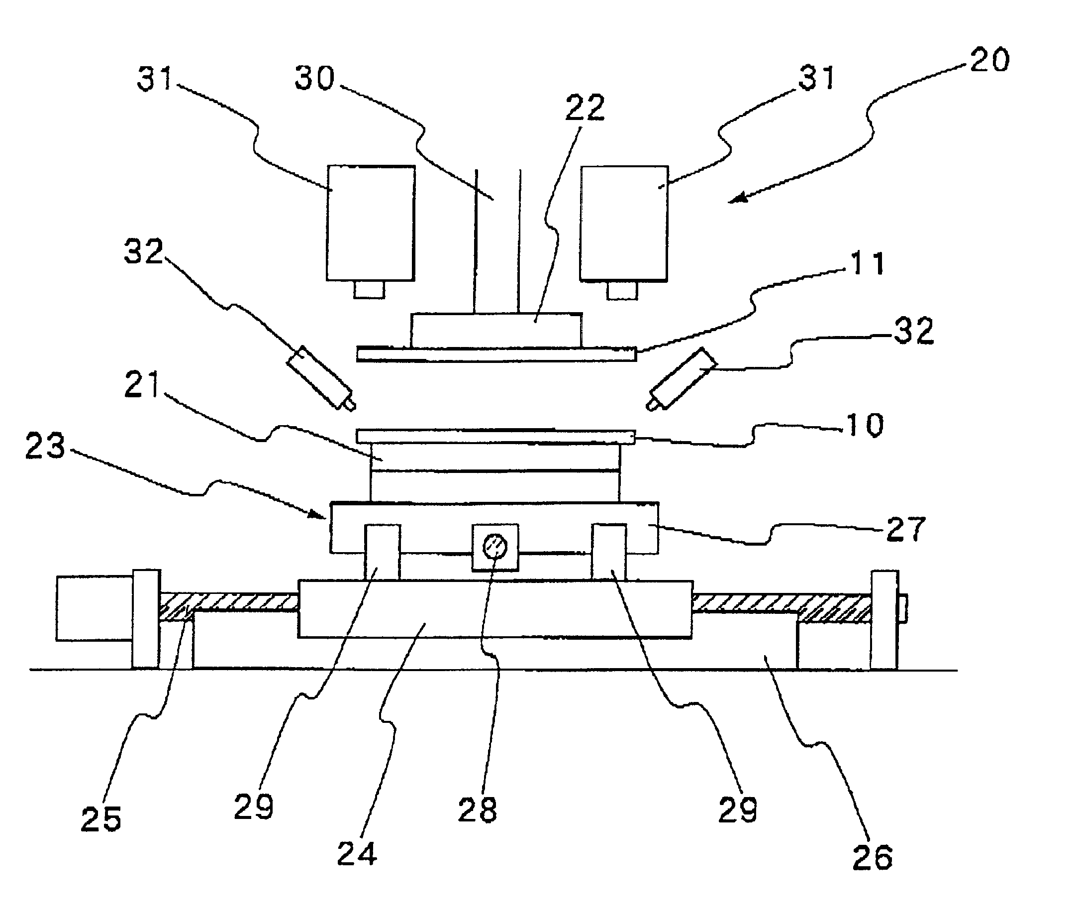
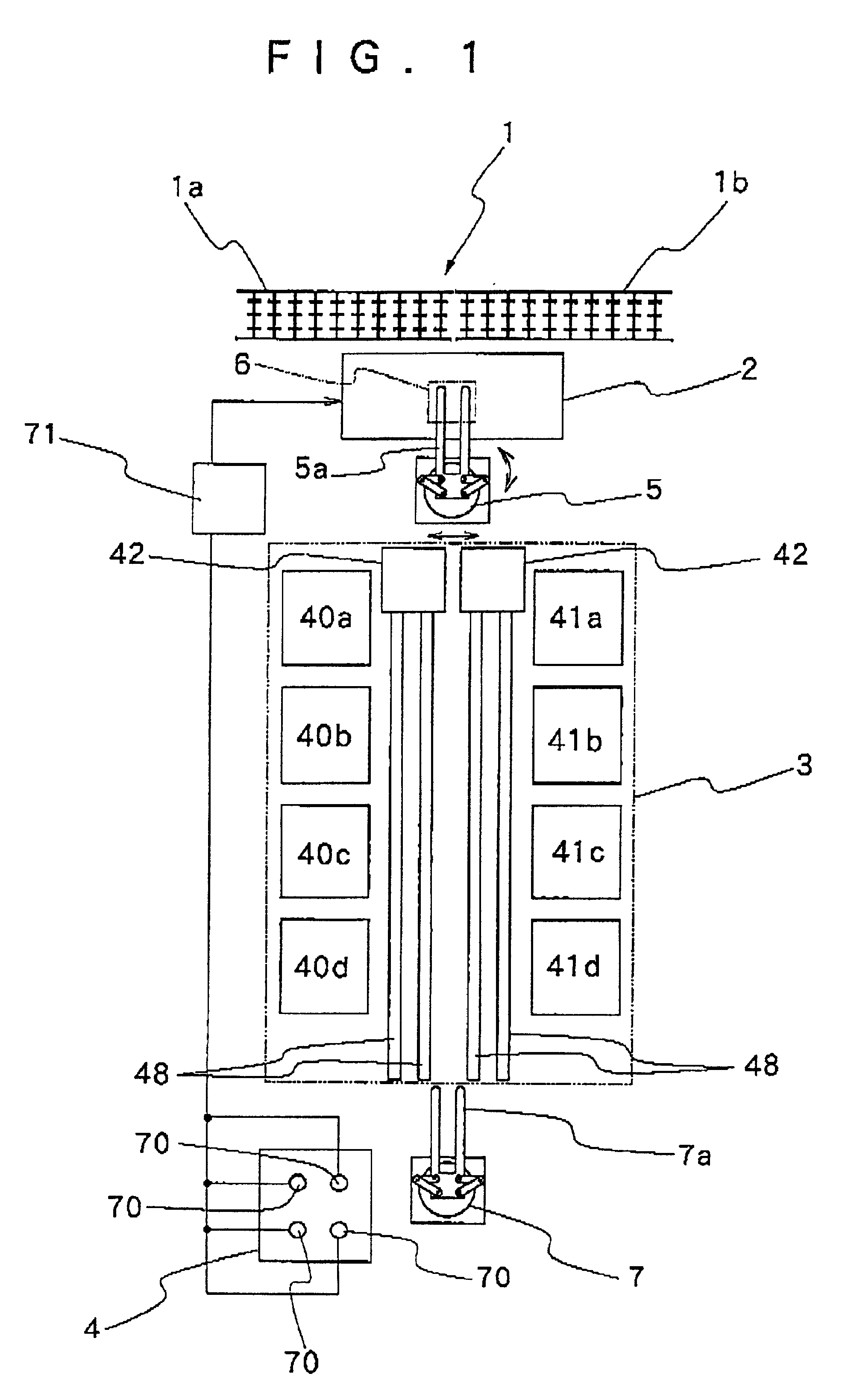
Hereafter, the present invention is described more particularly by way of its preferred embodiment with reference to the accompanying drawings. Reference is firstly had to FIG. 1 which shows general layout of a substrate bonding press according to the present invention. In this figure, indicated at 1 is a substrate conveyer, at 2 a provisional press station, at 3 a hot press station and at 4 an inspection station.

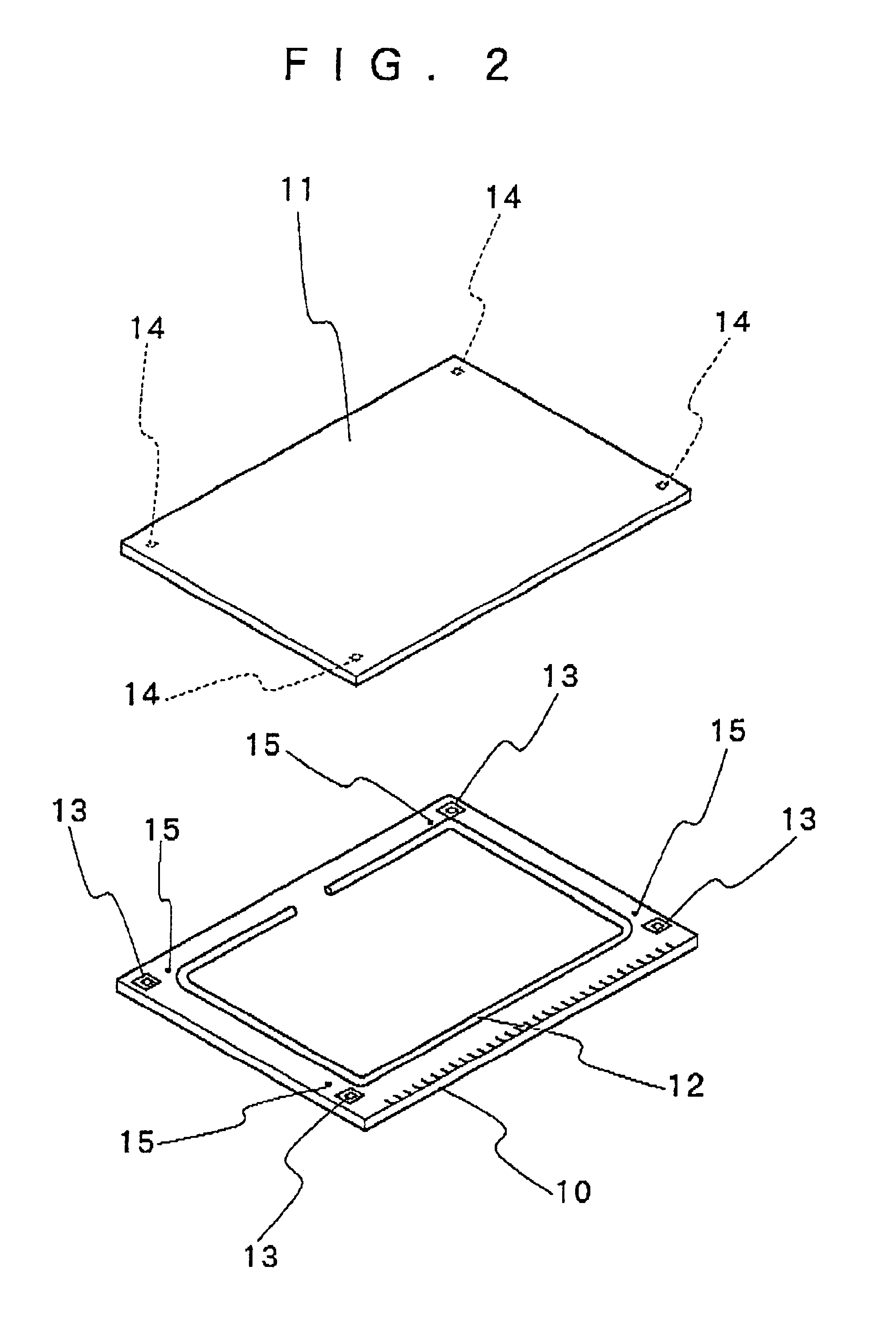
In FIG. 2, denoted at 10 and 11 are lower and upper substrates, for example, a TFT substrate and a filter substrate of an LCD panel, respectively. A sealer material 12 is applied on the lower substrate 10 before pressing. For example, the sealer material 12 is applied along marginal edges of the lower substrate plate 10 in a rectangular frame-like pattern with an open void portion at a predetermined position. After pressing and the two substrate plates 10 and 11 to adjust a gap space to a predetermined width, liquid crystal is sealed in the gap space through the open void p...


PUM

PropertyMeasurementUnit
widthaaaaaaaaaa
transparentaaaaaaaaaa
shapeaaaaaaaaaa

Abstract

Method and apparatus for registering and bonding upper and lower substrate plates together through a sealer material and in such a way as to form a gap of a predetermined width between the two substrate plates. Registered substrate plates are provisionally pressed to form a joined substrate assembly, which is then pressed under heated conditions at a hot press station, thereby compressing the sealer material into a flattened form and at the same time thermally hardening the sealer material to form a predetermined gap space between the two substrate plates. In order to correct positional deviations which occur to the upper and lower substrate plates in the course of the hot pressing, on the basis detected positional deviations of upper and lower substrate plates of a hot-pressed substrate assembly, upper and lower substrates are set in offset positions instead of aligned positions when registering them at the provisional press station to cancel predicted positional deviations at the hot press station.

Description

1. Field of the ArtThis invention relates to a method and an apparatus, for bonding substrate plates face to face in a predetermined gap relation through an interposed spacer material, and more particularly to a method and apparatus for bonding, for example, upper and lower substrate plates which form a liquid crystal cell of an LCD panel, strictly registering relative positions of the two substrate plates with each other and then pressing the substrate plates toward each other to compress and flatten the interposed sealer material to such a degree as to form a gap of a predetermined width between the upper and lower substrate plates.2. Prior ArtA liquid crystal cell of an LCD panel is formed by bonding together a couple of substrate plates of transparent synthetic resin material through a sea sealer material which is interposed between and along outer marginal edges of the substrate plates, and filling liquid crystal in a sealed gap space which is formed between the two substrate p...

Claims


Application Information

Patent Timeline
Patent Type & Authority Patents(United States)
IPC IPC(8): G02F1/13G02F1/1339G02F1/1333
CPCB32B38/1841G02F1/1339B32B2038/1891B32B2041/04Y10T156/1092G02F2001/133354B32B2457/202G02F1/133354
Inventor WATANABE, HIROYUKIOTSUBO, YUJISUGIZAKI, SHINJIICHIKAWA, HISAYOSHIKIYOMIYA, HIROAKI
Owner HITACHI ELECTRONICS ENG CO LTD
Why Eureka
Try Eureka