Waveguide-based optical chemical sensor

Inactive Publication Date: 2004-10-05
RGT UNIV OF CALIFORNIA
View PDF7 Cites 30 Cited by
  • Summary
  • Abstract
  • Description
  • Claims
  • Application Information

AI Technical Summary

Problems solved by technology

Many such sensors have one or more deficiencies

Method used


Image

  • Waveguide-based optical chemical sensor
  • Waveguide-based optical chemical sensor
  • Waveguide-based optical chemical sensor

Examples


Embodiment Construction

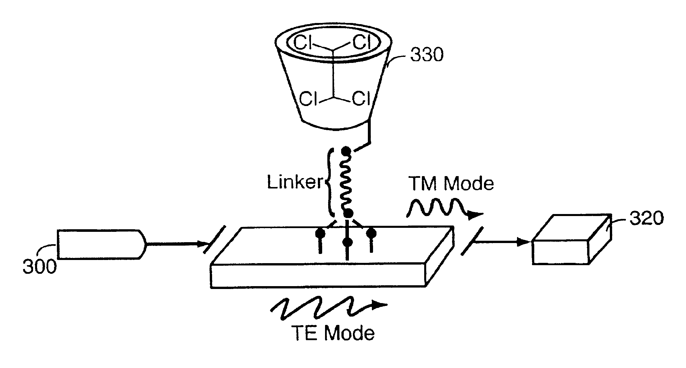
A sensor beam consisting of two collinear, orthogonally polarized modes of laser light having a small difference in frequency is produced by a laser or other laser light source. The beam is coupled into a planar optical waveguide. Species selective thin films of host reagents with cavity shaped molecules specifically tailored for optimized and reversible binding of targeted chemicals are covalently bound to the external surface of the waveguide. The host reagents form reversible inclusion complexes with the targeted molecules.

The index of refraction of the species-selective thin film of host reagent varies according to the number and kind of guest-host inclusion complexes formed in the film.

Each of the orthogonal modes of the beam propagating through the waveguide undergoes different changes in effective refractive index due to the formation of guest-host inclusion complexes on the surface of the waveguide. As a result there is phase retardation of one of the modes relative to the o...


PUM


Abstract

The invention provides an apparatus and method for highly selective and sensitive chemical sensing. Two modes of laser light are transmitted through a waveguide, refracted by a thin film host reagent coating on the waveguide, and analyzed in a phase sensitive detector for changes in effective refractive index. Sensor specificity is based on the particular species selective thin films of host reagents which are attached to the surface of the planar optical waveguide. The thin film of host reagents refracts laser light at different refractive indices according to what species are forming inclusion complexes with the host reagents.

Description

This invention relates to detection of specific chemical substances using species selective thin films, planar optical waveguides and laser interferometry.This invention was made with government support under Contract No. W-7405-ENG-36 awarded by the U.S. Department of Energy. The government has certain rights in the invention.There is an increasing need for gas sensors which can distinguish extremely low levels of particular gaseous species in the presence of large concentrations of interfering species.Several fiber optic and integrated optical transducers have been proposed as chemical sensors. Typically, such proposed sensors have been based on a change in the effective refractive index of a guided light mode due to a change in refractive index and / or a change in the thickness of a sensing overlayer. Many such sensors have one or more deficiencies in sensitivity, selectivity, or response time. Thus there is still a need for highly sensitive and selective gas sensors which operate...

Claims


Application Information

Patent Timeline
IPC IPC(8): G01N21/77G02B6/122G02B6/10G01N21/21
CPCG01N21/7703G02B6/1221G02B6/105G01N21/21G01N2021/7776G01N2021/7709
Inventor GRACE, KAREN M.SWANSON, BASIL I.HONKANEN, SEPPO
Owner RGT UNIV OF CALIFORNIA
Why Eureka
Try Eureka