Automatically adjusting annular jet mixer

a technology of automatic adjustment and annular jet mixer, which is applied in the direction of non-electric variable control, process and machine control, instruments, etc., can solve the problems of reduced viscosity, quality problems of guar gel, and not being fully utilized

Inactive Publication Date: 2004-10-12
SERVA CORP
View PDF13 Cites 34 Cited by
  • Summary
  • Abstract
  • Description
  • Claims
  • Application Information

AI Technical Summary

Benefits of technology

The pressure regulator sets the maximum pressure of the upstream side of the piston. This pressure, together with the area ratio of the control piston determines the mix water control pressure. If the mix water pressure is lower than required, then the piston moves the inner nozzle member in a direction that will reduce the nozzle outlet size. Reducing the nozzle size increases the backpressure. Conversely, if the mix water pressure is too high, then the piston will move the inner nozzle in the opposite direction to increase the nozzle opening and thus reduce the pressure.

Problems solved by technology

In the past, guar gel has had quality problems which were evident by lumps of partially hydrated gel within the gel fluid.
The reduced viscosity was caused by not all of the gel being incorporated into the fluid and thus not being fully utilized.
All these techniques added cost to the material, and depending on the process, added elaborate and expensive equipment.
All of these solutions added to the cost of fracturing a well, thus making the produced oil and gas more expensive.
Guar powder tends to lump if it is not fully wetted when it first encounters water.
One of the problems with standard mixers is that the nozzle or jet from which the water exits is usually fixed in size, i.e. the nozzle is not adjustable.
If the process rate is less than the optimal rate, then not enough energy will be created to mix the gel free of lumps.
In the process rate is much higher than the optimal rate, a high pressure loss is developed in the nozzle which increases required pump horse power and further limits the maximum throughput rate.

Method used


Image

  • Automatically adjusting annular jet mixer
  • Automatically adjusting annular jet mixer
  • Automatically adjusting annular jet mixer

Examples


Embodiment Construction

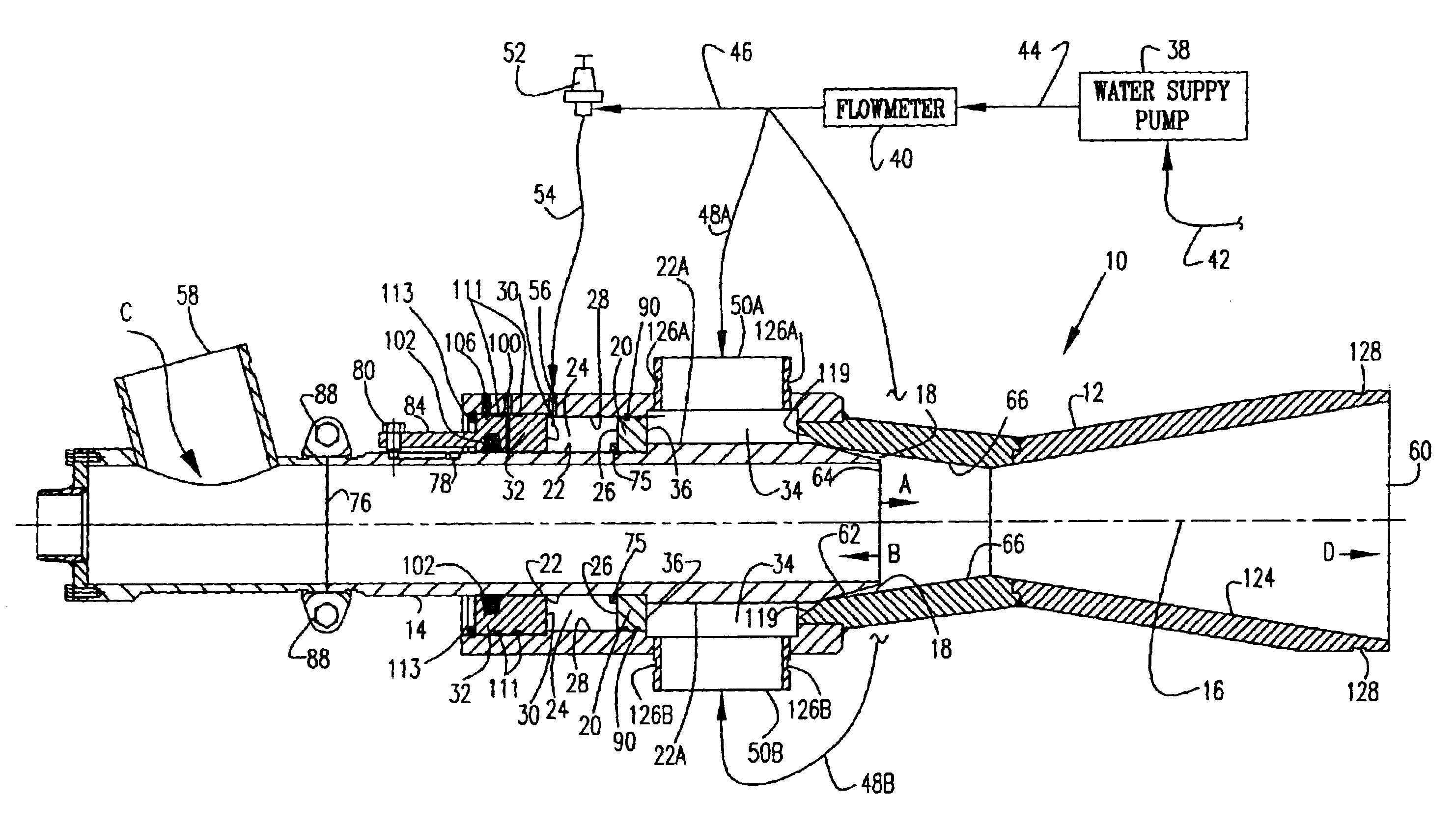
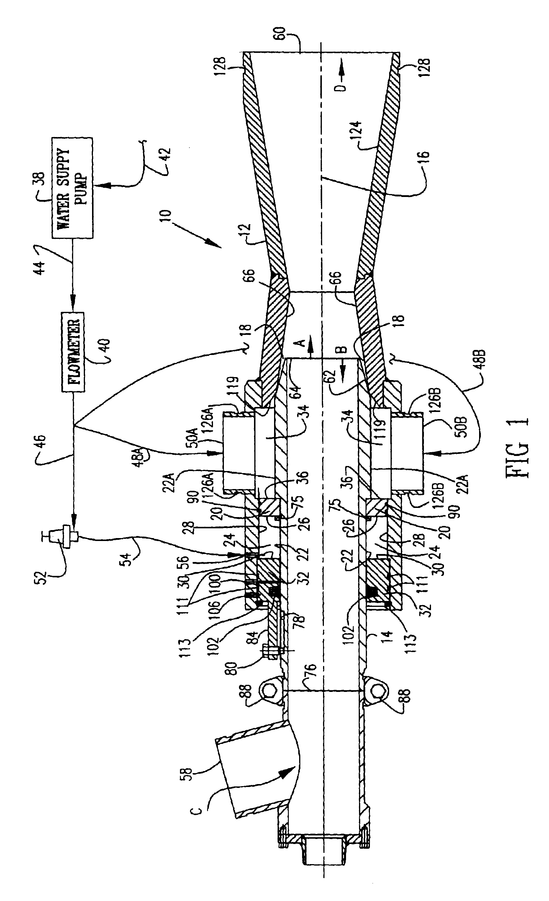
Referring now to the drawings and initially to FIG. 1, there is illustrated an automatically self adjusting annular jet mixer 10 that is constructed in accordance with a preferred embodiment of the present invention. The mixer 10 is a type that is useful in mixing guar and other materials to create a fracturing fluid gel at the site of a gas or oil well.

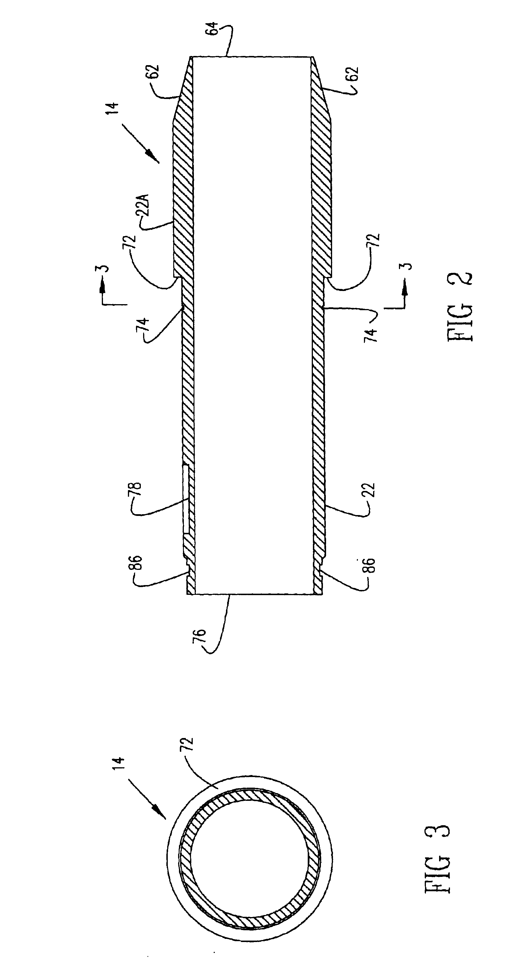
The mixer 10 is provided with a hollow stationary housing 12 and a hollow inner nozzle member 14 that is axially movable along a centerline 16 of the mixer 10 in order to increase and decrease the size of the effective nozzle opening 18. A piston 20 is integrally attached to the inner nozzle 14. The piston 20 encircles an external surface 22 of the inner nozzle 14 so that an enclosed upstream cavity 24 is formed between a first side 26 of the piston 20, the external surface 22 of the inner nozzle 14, an inner surface 28 of the housing 12, and a first end 30 of an alignment member 32. Also an enclosed downstream cavity 34 is formed on...


PUM

PropertyMeasurementUnit
pressureaaaaaaaaaa
constant pressureaaaaaaaaaa
permeabilityaaaaaaaaaa

Abstract

An automatically adjusting jet mixer used in mixing fracturing fluid gel for gas and oil wells. The mixer has an inner nozzle and an attached piston that move axially within the mixer's housing to change the size of the nozzle opening thorough which mix water enters the mixer. One side of the piston has an upstream area and an opposite side has a downstream area. The downstream area is connected to the mix water supply pump and the upstream area is connected to the outlet of a pressure regulator that maintains a constant pressure in the upstream area. The piston and the nozzle move via hydraulic pressure exerted on the piston in proportion to the change in pressure in the downstream area to a position that will maintain a constant mixing jet pressure, thus providing constant specific mixing energy, i.e. constant energy per unit mass of fluid.

Description

1. Field of the InventionThe present invention relates to an automatically self adjusting annular jet mixer useful in mixing guar and other materials to create a fracturing fluid gel at the site of a gas or oil well.2. Description of the Related ArtMixing of guar and other material for creating a fracturing fluid gel has been known for approximately 50 years. Fracturing fluids are used to carry or transport proppant, usually sand, into a well fracture for the purpose of creating improved production of hydrocarbons, i.e. oil or natural gas. In the past, guar gel has had quality problems which were evident by lumps of partially hydrated gel within the gel fluid. These lumps could possible plug off formation permeability and also caused reduced viscosity of the gel. The reduced viscosity was caused by not all of the gel being incorporated into the fluid and thus not being fully utilized. Many efforts, some quite elaborate, have been used to produce a quality gel, i.e. one that was free...

Claims


Application Information

Patent Timeline
Patent Type & Authority Patents(United States)
IPC IPC(8): B01F5/04B01F15/00B01F3/12
CPCB01F5/0475B01F15/00357B01F5/049B01F3/12B01F15/00123B01F23/50B01F25/3142B01F25/31432B01F35/20B01F35/2213
Inventor ALLEN, THOMAS E.
Owner SERVA CORP
Why Eureka
Try Eureka