Vascular inducing implants

a technology of inducing implants and vascular insufficiency, which is applied in the field of vascular inducing implants, can solve the problems of inability to heal, tissue injury, and tissue damage, and achieve the effects of tightness, reduced diameter, and increased profil

Inactive Publication Date: 2004-10-12
CR BARD INC
View PDF167 Cites 74 Cited by
  • Summary
  • Abstract
  • Description
  • Claims
  • Application Information

AI Technical Summary

Benefits of technology

Implant embodiments may further be prepared to initiate angiogenesis by having a thrombus of blood associated with them at the time of their implantation or inserted in the interior immediately following implantation. The thrombus of blood may be taken from the patient prior to the implant procedure and is believed to help initiate the tissue's healing response which leads to angiogenesis.
By way of example, the implant device may comprise a helical spring having a first configuration that is more tightly wound, having an elongated length, more coils and a reduced diameter The second configuration of the spring will provide an increased profile by increasing the diameter of the coils through shortening the length of the spring.
In another embodiment, the implant may have a first configuration that is uniaxial and a second configuration that is biaxial or bifurcated to provide an increased profile. The bifurcated embodiments disclosed may be comprised of single or double helical coils arranged to have a trunk portion and two leg portions. The resulting appearance is similar to a pair of pants. Alternatively, the bifurcated embodiment may be configured as two spines having loops mounted concentrically along their length, the spines being joined to several common loops at one end to form a trunk portion, and the other ends of the spine being free to form the leg portions of the implant. In both bifurcated implant embodiments, the loops or coils are interleaved while maintained in the first configuration such that they lie substantially along the same axis. In the second configuration, the spines spring apart to form a Y-shaped or bifurcated configuration presenting a larger profile to increase the injury to surrounding tissue and initiate angiogenesis.
It is another objective of the present invention to provide an implant delivery system that is safe and simple to use while minimizing trauma to the patient.

Problems solved by technology

Expansion of the device to the larger profile configuration not only places stress on the tissue but serves to rupture and injure the tissue slightly as it expands.
However, the magnitude of the expansion to the second configuration is not so great that tissue becomes severely injured: function impaired and unable to heal.
As tissue surrounding the implant moves, such as the contraction and relaxation of muscle tissue, some friction and abrasion from the implant occurs, which injures the tissue.

Method used


Image

  • Vascular inducing implants
  • Vascular inducing implants
  • Vascular inducing implants

Examples


Embodiment Construction

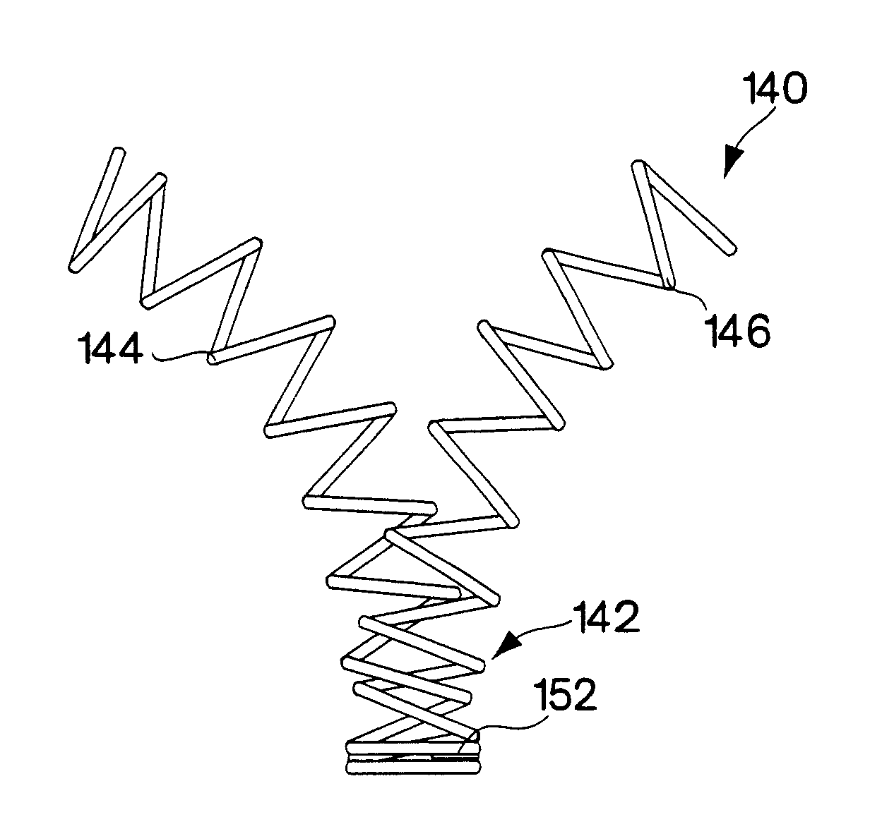
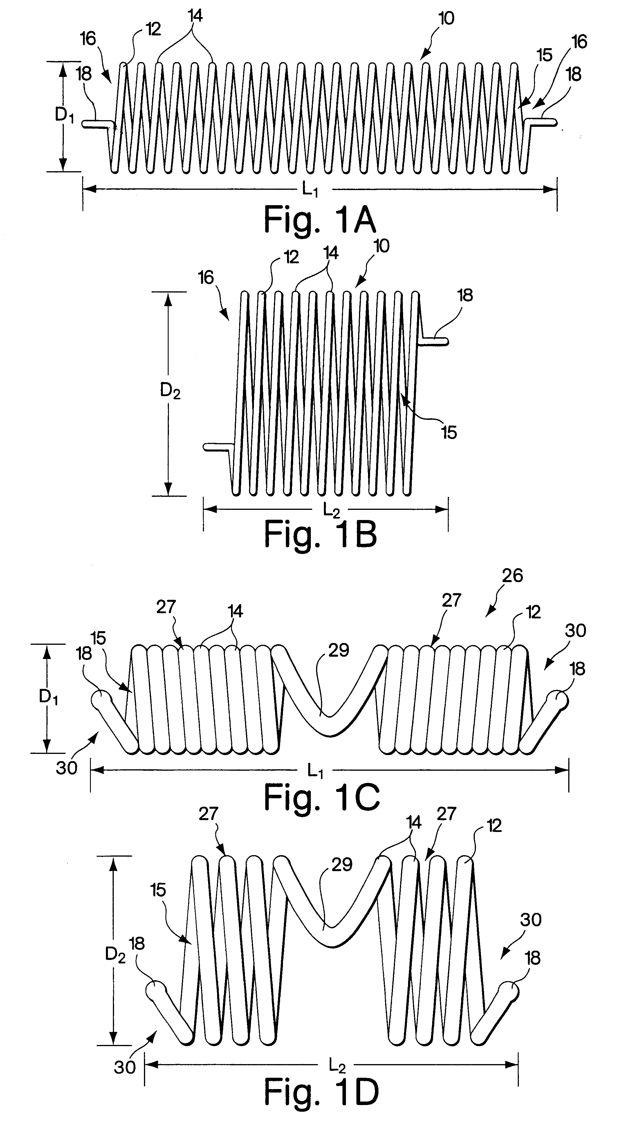
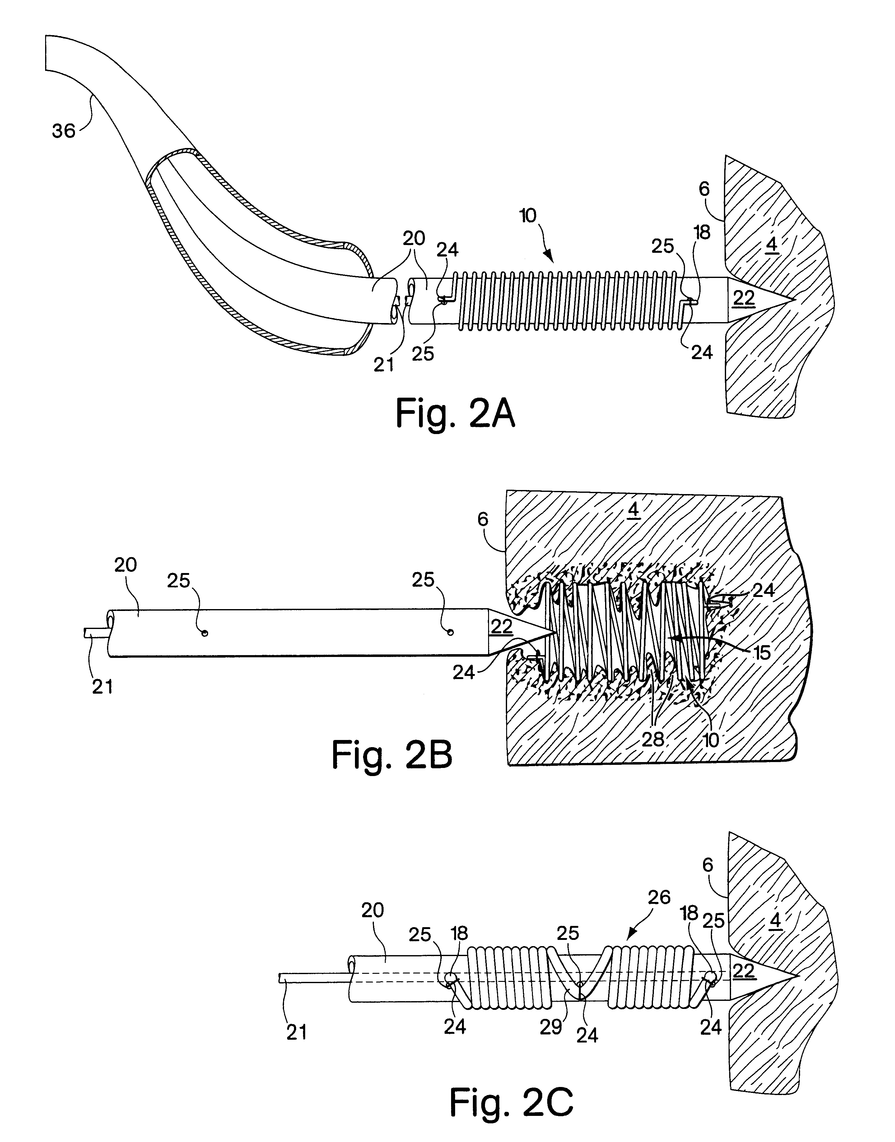
FIGS. 1A and 1B show a first embodiment of the implant comprising a helical coil spring 10. The spring is formed from a filament 12 of flexible material such as stainless steel or other metal or high density polymer. The filament is helically wrapped to form several individual coils 14 that comprise a spring having an interior 15. At each end 16 of the spring, the filament 12 terminates with a small tab 18 extending in a plane parallel to the axis of the implant. The tabs 18 are used for maintaining the implant upon the delivery device as will be described in further detail below. FIGS. 1C and 1D show an alternative spring implant embodiment 26 comprised of two segments 27 that are wound in opposite directions and joined together by a bridge 29. Each segment has a free end 30 in which the filament 12 terminates in a bulbous tab 18.

The spring implant embodiments are easily arranged from a first configuration to a second configuration, where the second configuration of the implant has...


PUM


Abstract

Implants and associated delivery systems for promoting angiogenesis in ischemic tissue are provided. The implants may be delivered percutaneously, thoracically or surgically and are particularly well suited for implantation into the myocardium of the heart. The implants are configured to have a first configuration having a low profile and an expanded, second configuration having a large profile. The implants are delivered to the ischemic tissue location in the first configuration, implanted then expanded to the second configuration. The expanded implants maintain a stress on the surrounding tissue, irritating and slightly injuring the tissue to provoke an injury response that results in angiogenesis. The flow of blood from the surrounding tissue into the implant and pooling of the blood in and around the implant leads to thrombosis and fibrin growth. This healing process leads to angiogenesis in the tissue surrounding the implant. Additionally, the implants may contain an angiogenic substance or a thrombus of blood, preloaded or injected after implantation to aid in initiating angiogenesis.

Description

FIELD OF THE INVENTIONThis invention relates to methods and devices for inducing angiogenesis in ischemic tissue.BACKGROUND OF THE INVENTIONTissue becomes ischemic when it is deprived of oxygenated blood. Blood may be present in such tissue, though it is not carrying oxygen. Ischemic tissue can be revived to function normally if it has remained viable despite the deprivation of oxygenated blood. Ischemia can be caused by a blockage in the vascular system that prohibits oxygenated blood from reaching the affected tissue area. Ischemia causes pain in the area of the affected tissue and in the case of muscle tissue can interrupt muscular function.Although ischemia can occur in various regions of the body, often tissue of the heart, the myocardium, is affected by ischemia due to coronary artery disease, occlusion of the coronary artery, which otherwise provides blood to the myocardium. Muscle tissue affected by ischemia can cause pain to the individual affected. Ischemia can be treated,...

Claims


Application Information

Patent Timeline
Patent Type & Authority Patents(United States)
IPC IPC(8): A61F2/06A61F2/00A61F2/02A61B17/00A61F2/94A61M37/00
CPCA61F2/06A61F2/2493A61F2/94A61B17/00234A61B2017/00243A61F2250/0067A61F2230/0091A61F2220/0016A61F2220/005A61F2220/0058A61F2230/0076
Inventor GAMBALE, RICHARD A.FORCUCCI, STEPHEN J.WEISER, MICHAEL F.CHOH, RICHARD T.FORDE, SEAN
Owner CR BARD INC
Why Eureka
Try Eureka