Fast sweep voltage ramp generator and streak camera using same

a speed scanning voltage and ramp generator technology, applied in pulse generators, pulse generation by avalanche-like devices, electric pulse generator circuits, etc., can solve the problems of high impedance output, limit of technology, and complicated ramp generators obtained according to known ar

Inactive Publication Date: 2004-10-26
COMMISSARIAT A LENERGIE ATOMIQUE ET AUX ENERGIES ALTERNATIVES
View PDF4 Cites 14 Cited by
  • Summary
  • Abstract
  • Description
  • Claims
  • Application Information

AI Technical Summary

Problems solved by technology

All ramp generators thus obtained according to known art are usually complicated, close to the limits of the technology and furthermore very frequently have a high impedance output.

Method used


Image

  • Fast sweep voltage ramp generator and streak camera using same
  • Fast sweep voltage ramp generator and streak camera using same
  • Fast sweep voltage ramp generator and streak camera using same

Examples


Embodiment Construction

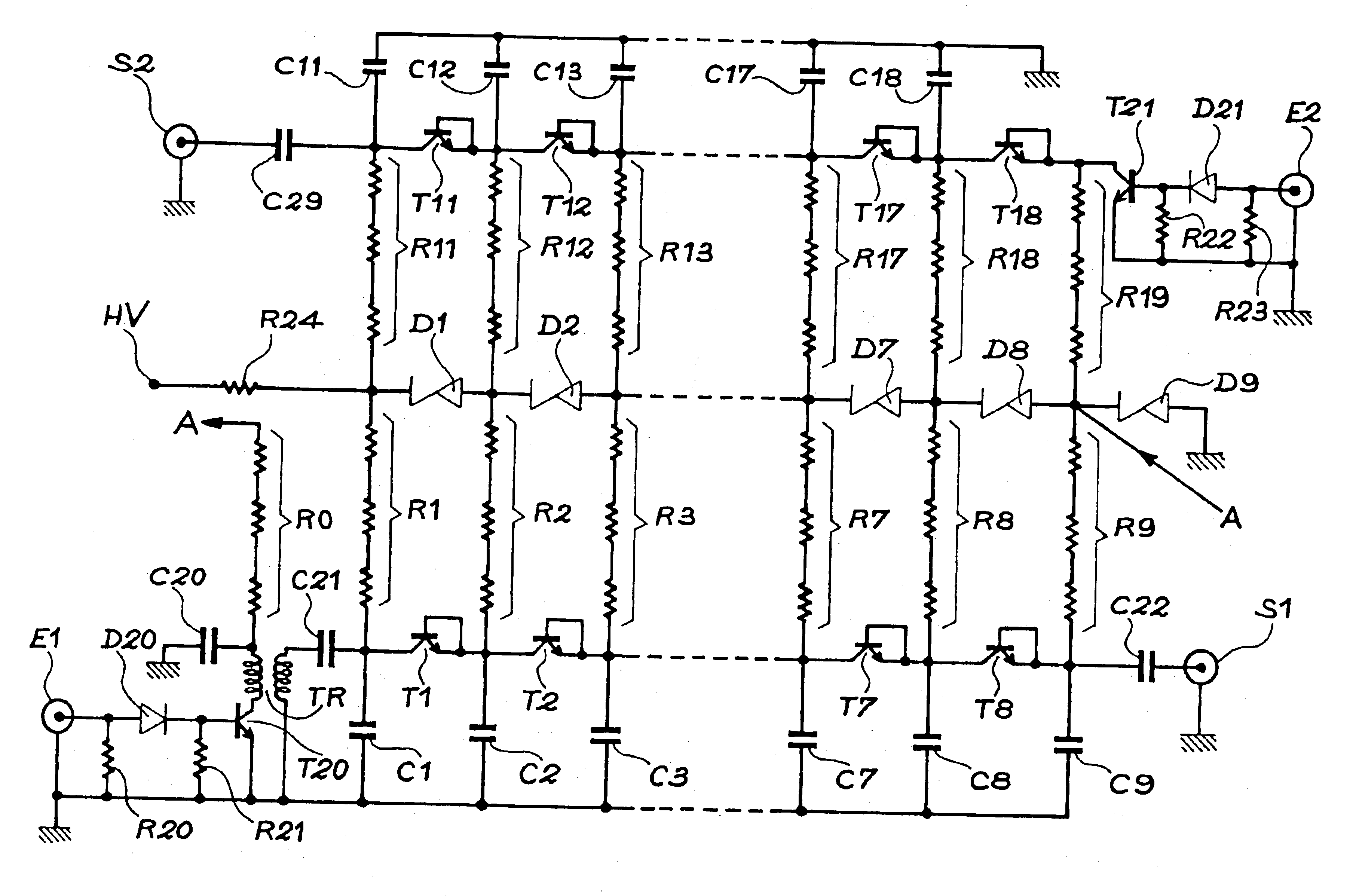
The ramp generator according to the invention uses avalanche transistor chains. This type of avalanche transistor is a two-pole transistor that has a collector current-collector voltage characteristic with a negative slope, when the base-emitter resistance is low. It forms a very fast switch which closes controlled either by the base or by exceeding the limiting voltage of the collector. In the latter case, the base and the emitter are connected together. Operation of this transistor is then similar to operation of a conventional splitter. The invention only uses this second case.

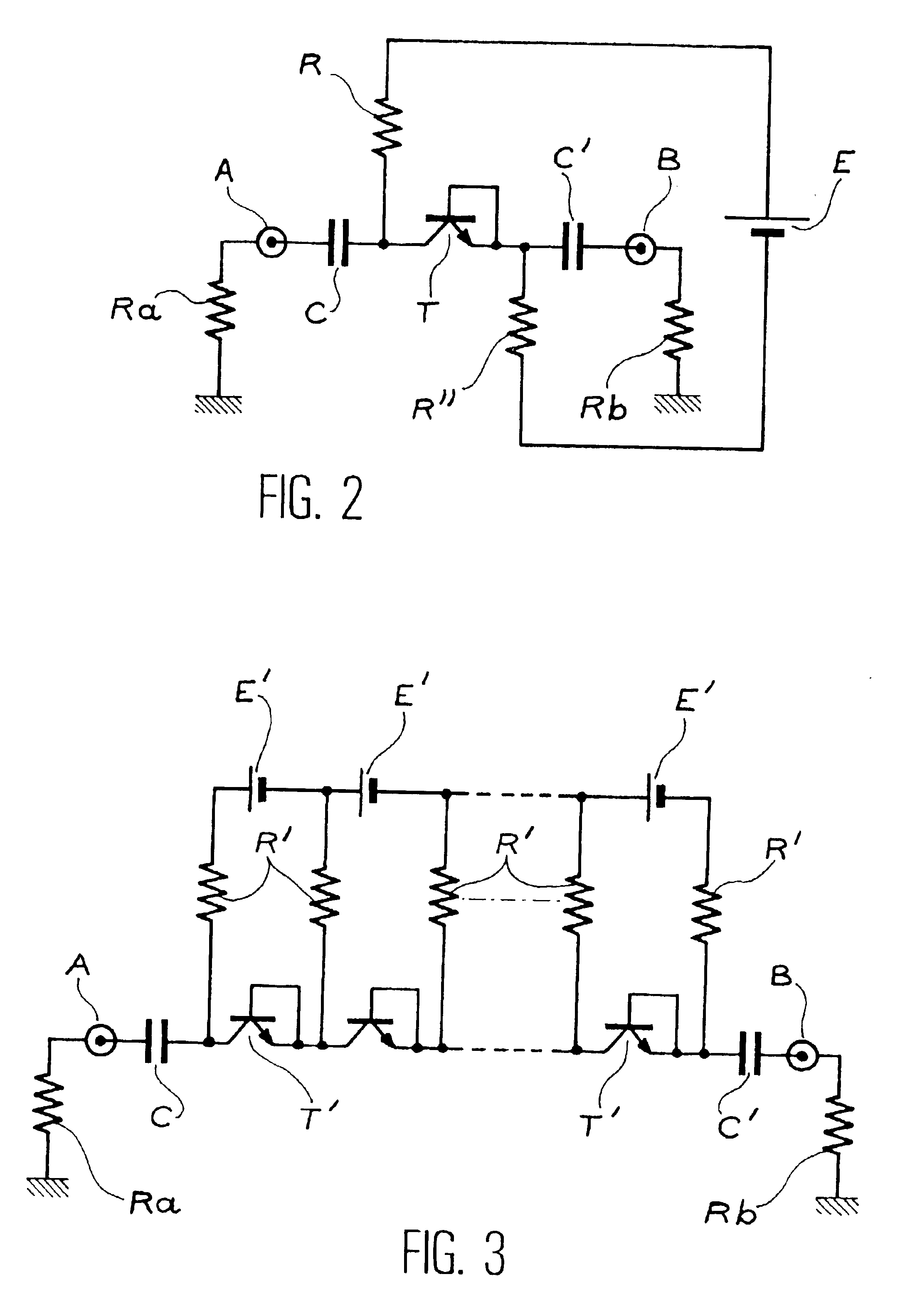
FIG. 2 illustrates the installation of such an avalanche transistor T. The base and the emitter of this transistor T are connected together. The collector of this transistor is connected firstly to the ground through a capacitor C and a resistance Ra, and secondly to the + terminal of a DC source E through a resistance R. The emitter of this transistor is connected firstly to the ground through a capacitor ...


PUM


Abstract

A fast scanning voltage ramp generator including at least one chain of N two-pole avalanche transistors in series and a set of N+1 zener diodes in series between a high voltage power supply and ground, where N is an integer number.gtoreq.2. A streak camera can utilize this type of generator.

Description

TECHNICAL DOMAINThe invention relates to a fast scanning voltage ramp generator and a streak camera using such a generator.STATE OF PRIOR ARTAs described in "Improvement in avalanche--transistor sweep circuitry for electropic streak cameras" by S. W. Thomas, R. L. Griffith and W. R. McDonald (16.sup.th International Congress. "High Speed Photography and Photonics". Strasbourg, Aug. 27-31, 1984) streak cameras used for the diagnostic of fast photonic phenomena (in visible light or X-rays) are composed of a photocathode that converts photons into electrons, an electron acceleration and deviation system, and an image recovery system.FIG. 1 diagrammatically illustrates such a streak camera that includes:a photocathode 10,a horizontal slit 11,two deflection plates 12,an anode 13,an image recovery system 14.In this type of camera, the basic phenomenon as a function of time is spread on the recovery screen 14. It is transformed into a function of a distance. The use of such a camera requir...

Claims


Application Information

Patent Timeline
Patent Type & Authority Patents(United States)
IPC IPC(8): H03K3/335H03K3/00
CPCH03K3/335
Inventor SCHAAL, ALFRED
Owner COMMISSARIAT A LENERGIE ATOMIQUE ET AUX ENERGIES ALTERNATIVES
Why Eureka
Try Eureka