Apparatus for launching heavy large payloads from an aircraft

a technology for aircraft and payloads, applied in the field of aerospace engineering, can solve the problems of large lateral loads (reactions) acting on payloads, the need to provide new large extraction parachutes or unreliable multi-canopy systems made of existing extraction parachutes, and the provision of maximum load-carrying, so as to reduce the structural mass of payloads and increase the load-carrying capacity. , the effect of reducing the lateral loads

Inactive Publication Date: 2004-11-02
AIR LAUNCH AEROSPACE CORP
View PDF17 Cites 0 Cited by
  • Summary
  • Abstract
  • Description
  • Claims
  • Application Information

AI Technical Summary

Benefits of technology

The objects of the present invention are to reduce lateral loads acting on heavy large payloads when they are launched from an aircraft, therefore, reduce the structural mass of the payloads, such as missile vehicles, increase their load-carrying capacity and reduce the specific cost of launching the payload, as well as provide the aircraft and its crew safety at the launching stage.
To damp vibrations in the calibrated legs and reduce dynamic structural loading on the payload to be launched, the calibrated legs comprise dynamic vibration dampers for damping dynamic vibrations of the payload being launched when it leaves the launching container.

Problems solved by technology

Disadvantages of the prior art launching apparatuses include the necessity to use special platforms and extraction parachutes, which are expandable.
This prohibits e.g. the provision of maximum load-carrying capacity to put into orbit for the air-start missile vehicles launched from an aircraft.
A significant disadvantage of the prior art methods is the necessity to provide new large extraction parachutes or unreliable multi-canopy systems made of the existing extraction parachutes for such heavy payloads.
The problems with the above prior arts include considerable lateral loads (responses) acting on the payload to be launched from the mounting members.
In addition, at the final step of the payload exit from the launching container, e.g. when two belts of the mounting members remain in the container, the payload being launched can be wedged or undergo inadmissibly increased loads from the mounting members.
With heavy large payloads to be launched, such as missile vehicles, the great lateral loads necessitate strengthening the missile vehicle structure, which increases the weight thereof, reduces the load-carrying capacity and raises the specific cost of the payload launched.

Method used


Image

  • Apparatus for launching heavy large payloads from an aircraft
  • Apparatus for launching heavy large payloads from an aircraft
  • Apparatus for launching heavy large payloads from an aircraft

Examples


Embodiment Construction

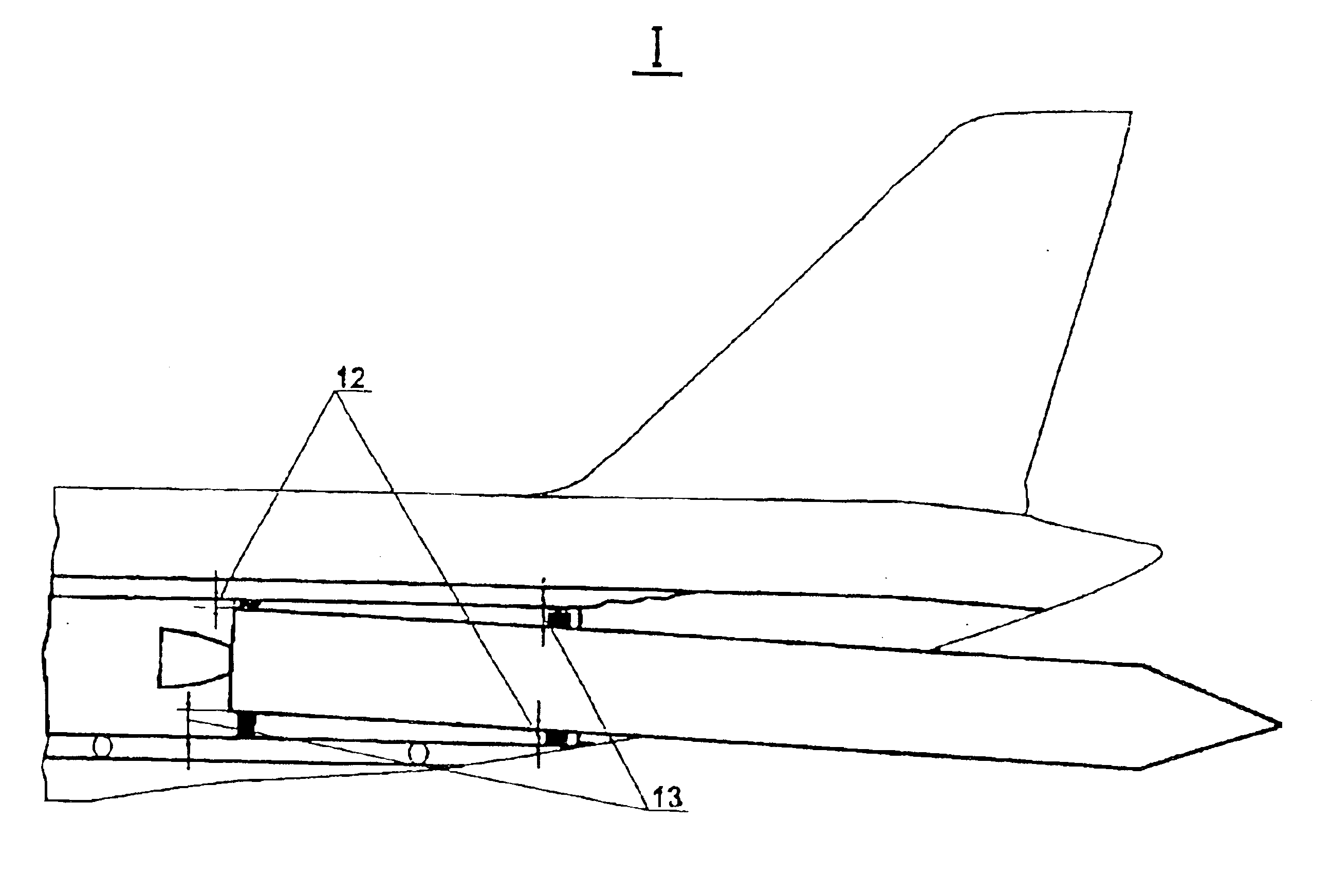
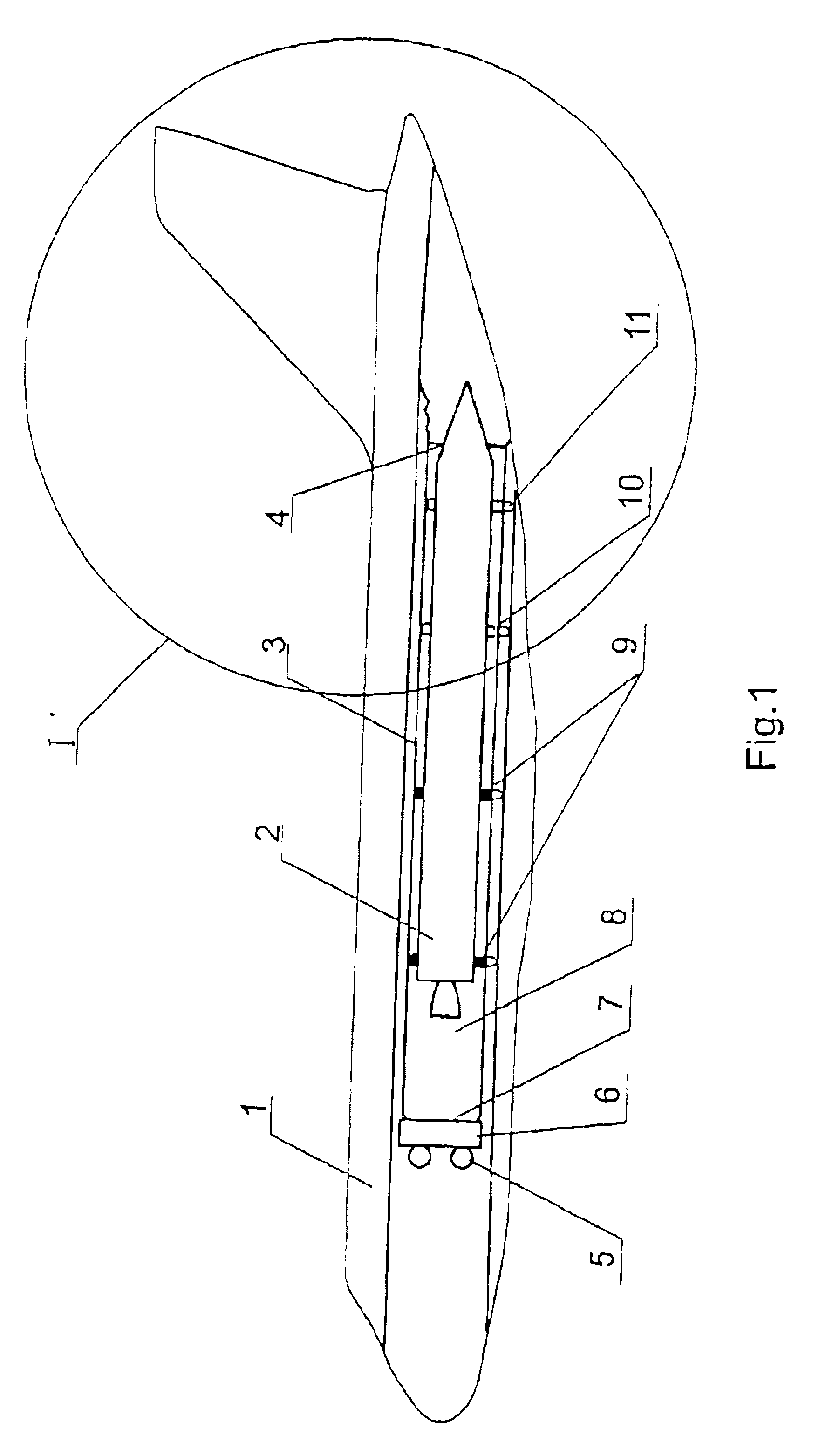
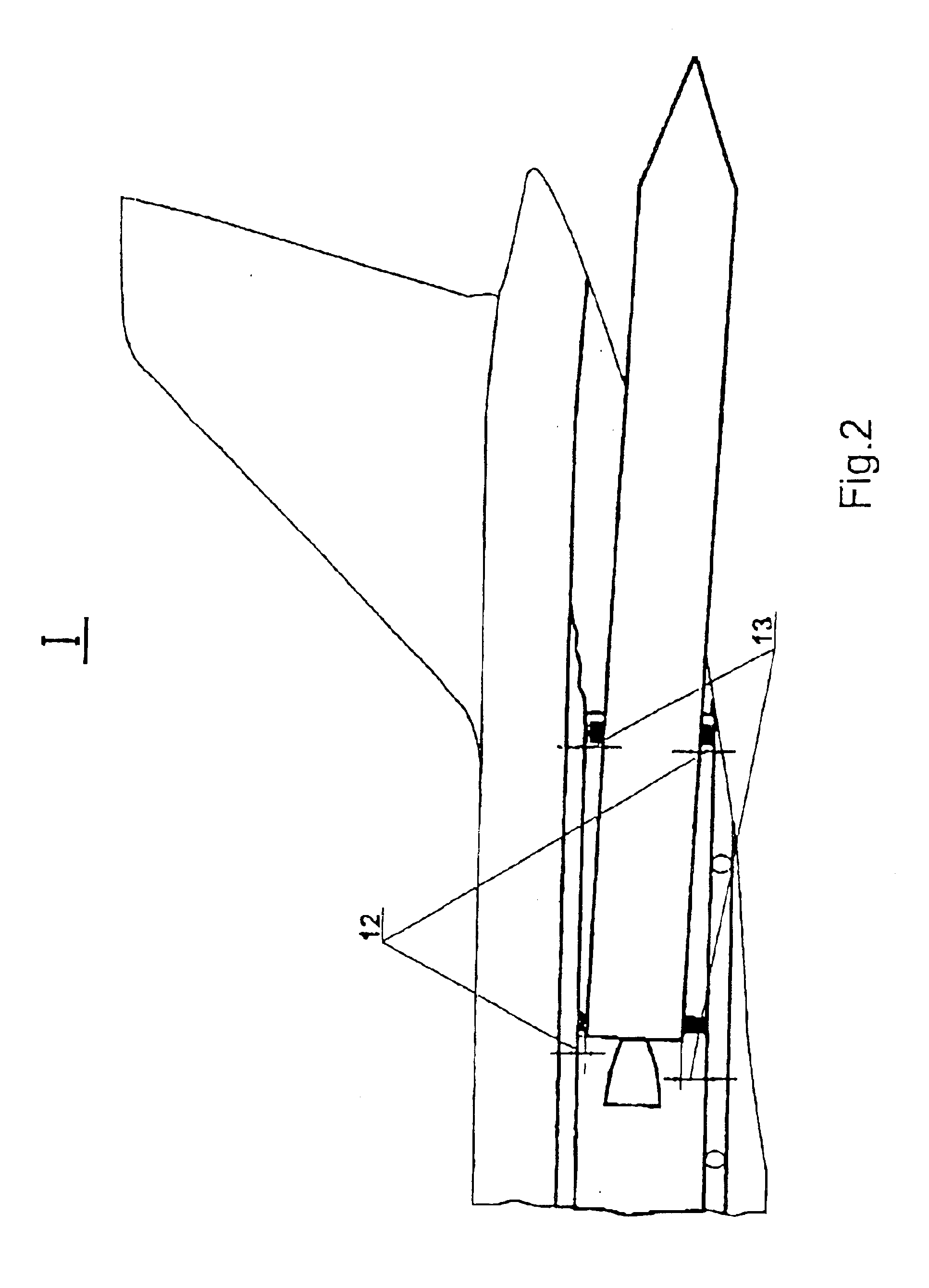
FIGS. 1, 2, 3 and 4 illustrate an embodiment of securing the mounting members on a payload to be launched. The calibrated legs are located on the belts maximum distant from an open end of the launching container.

In accordance with the present invention, an apparatus for launching heavy large payloads 2 from an aircraft 1 comprises a launching container 3 with an open end 4, a pneumatic expulsion device 6 for expelling a payload from the container 3 through the open end 4, and a pressurization source 5. The payload 2 to be launched is located inside the launching container 3 on mounting members 10 disposed on at least two belts of the payload 2 to be launched. At least one of the mounting members 10 is a calibrated leg 9.

The calibrated legs 9 are located on the belts of maximum distant from the open end 4 of the launching container 3, if the mounting members, including the calibrated legs, are secured on the payload 2 to be launched. In another embodiment, with the mounting members 1...


PUM


Abstract

The invention relates to the aerospace engineering and can be used for jettisoning boost rockets from an aircraft. The inventive device comprises a landing container (3) with an open end (4) provided with a high-pressure source (5). The freight to be jettisoned (2) is arranged in two sections inside the container (3) on mounting elements (10), one of which is embodied in the form of a calibrated support (9). The values of maximum efforts and acceptable lateral movements (13) of the supports (9) are chosen in such a way that a minimum positive allowance (12) between the container (3) and the freight (2) is provided. The supports (9) are provided with dampers. The aim of the invention is to reduce a transverse load affecting the freight to be jettisoned landing.

Description

1. Field of the InventionThe present invention relates to aerospace engineering and is applicable in launching missile vehicles and other heavy large payloads from aircraft to urgently deliver them to remote parts of the Earth and the ocean.2. State of the ArtConventional apparatuses for launching missile vehicles from an aircraft use extraction parachutes.By way of example, in 70th the U.S.A carried out launching mock-ups and Minitmen-1, ICBMs removed from the weaponry, from S-5A military aircraft to demonstrate the air-basing capabilities thereof (Rocket and Space Engineering, 1974, No. 6, pages 1 to 6). A missile on a special take-off platform was mounted on roll-tables in the freight compartment of the S-5A aircraft. The platform with the missile was released through the rearward port of the aircraft by two extraction parachutes. The parachute deployment and extraction of the missile from the freight compartment took more than 6-8 seconds. After a lapse of time from the release ...

Claims


Application Information

Patent Timeline
Patent Type & Authority Patents(United States)
IPC IPC(8): B64D1/00B64G1/00B64D1/10B64D1/12B64D7/00B64D5/00B64D7/08F41F3/06F41F3/00B64D1/04
CPCB64D1/10B64D1/12F41F3/06B64D7/08B64G1/005B64D5/00
Inventor KARPOV, ANATOLY STEPANOVICHIVANOV, ROBERT KONSTANTINOVICHMONAKHOV, JURY VLADIMIROVICHKOVALEVSKY, MIKHAIL MARKOVICHBORISOV, ANDREY VLADIMIROVICHPOLYAKOV, BORIS ALEXANDROVICHMASHUROV, SERGEY SEMOVICH
Owner AIR LAUNCH AEROSPACE CORP
Why Eureka
Try Eureka