
Glass composition for an electric lamp, stem and bulb for an electric lamp using the same, and electric lamp using the same

a technology of glass composition and electric lamps, applied in the direction of gas discharge lamps details, etc., can solve the problems of glass breakage, electric lamps are likely to be broken during manufacturing processes, and the thermal expansion coefficient of glass becomes too low

Inactive Publication Date: 2004-11-02
PANASONIC CORP
View PDF22 Cites 13 Cited by
  • Summary
  • Abstract
  • Description
  • Claims
  • Application Information

AI Technical Summary

Benefits of technology

The glass composition significantly reduces breakage during processing, maintains necessary thermal and electrical properties, and is suitable for complex lamp shapes, including bent and connected tube designs, thereby improving manufacturing efficiency and product reliability.

Problems solved by technology

However, conventional alternative glass compositions as described above are too brittle compared with lead glass, and thus the electric lamps are likely to be broken during manufacturing processes.
These processes, namely processes in which glass that has already been formed further is processed, cause breakage of the glass.
However, when the content of SiO.sub.2 is too high, the softening temperature of the glass becomes too high to allow shaping of the glass, and further, the thermal expansion coefficient of the glass becomes too low.
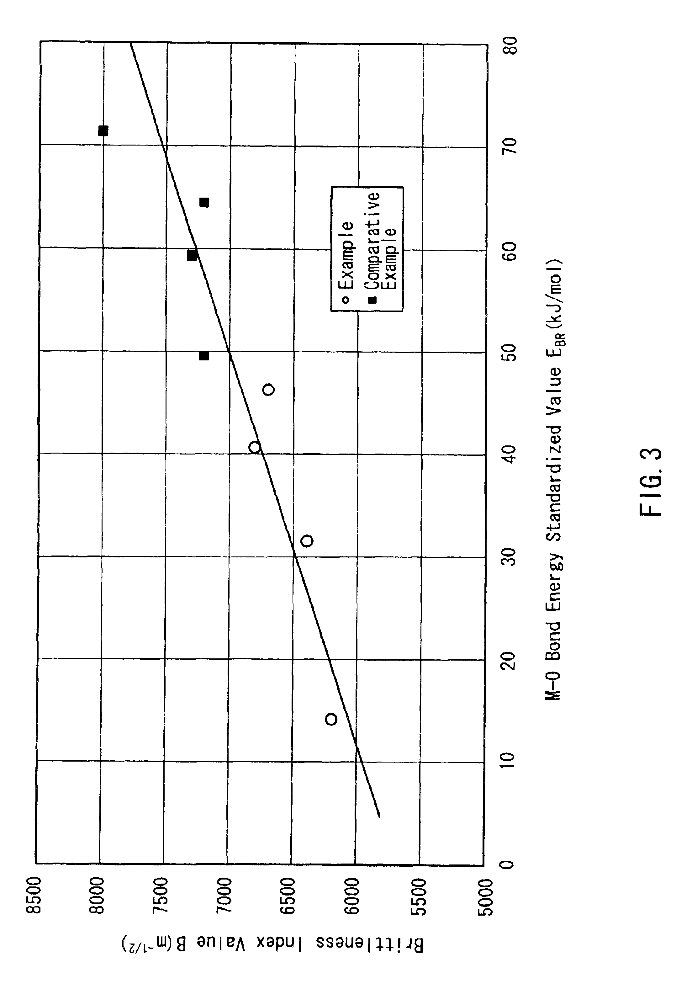
The higher bond energy with an oxygen atom a metal has, the more the metal increases the brittleness when compared in a unit content.
When a total content of alkaline-earth metal oxides is too low, the chemical resistance or the like of the glass is overly decreased.
When the glass has an excessively low electric resistance value, an insulation property of the glass disappears.

Method used


Image

  • Glass composition for an electric lamp, stem and bulb for an electric lamp using the same, and electric lamp using the same
  • Glass composition for an electric lamp, stem and bulb for an electric lamp using the same, and electric lamp using the same
  • Glass composition for an electric lamp, stem and bulb for an electric lamp using the same, and electric lamp using the same

Examples


Embodiment Construction

Various types of glass having compositions shown in Tables 2 and 3 were manufactured and evaluated for their respective properties. Specifically, in each case of these types of glass, glass materials that had been mixed so as to give a predetermined composition were put in a platinum pot. The mixed glass materials were melted in an electric furnace. Then, the glass materials were poured onto a carbon plate and allowed to cool.

TABLE 3

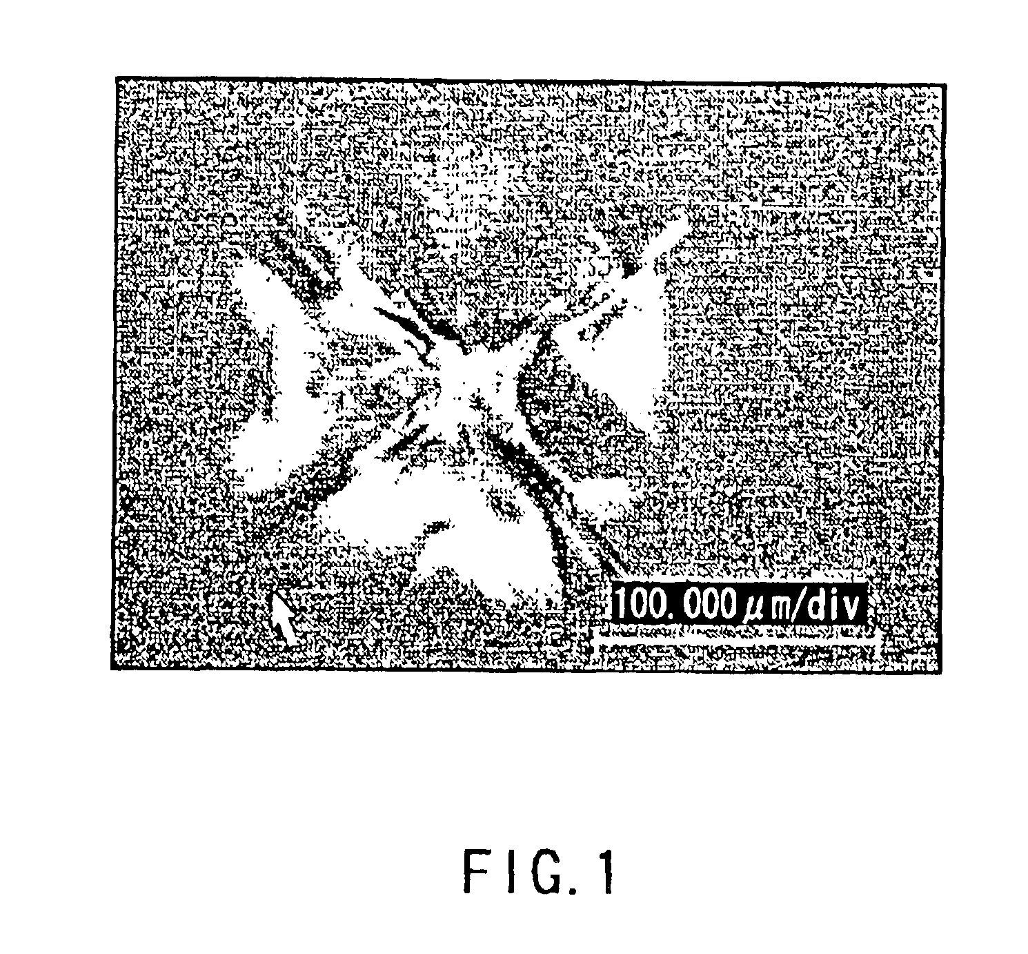
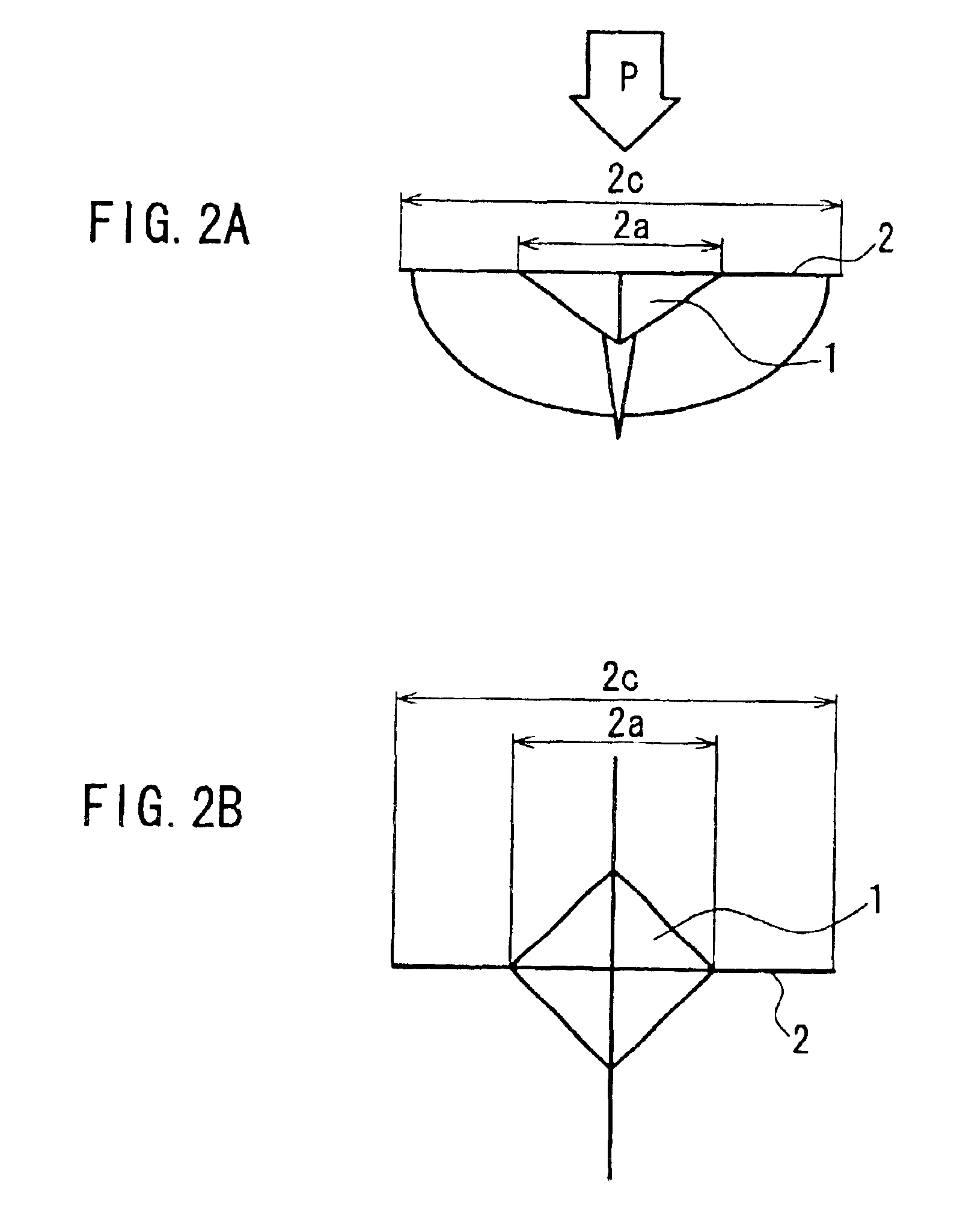
In the tables, a thermal expansion coefficient .alpha. represents values determined by measurements performed at temperatures of 30 to 380.degree. C. based on JIS R 3102. As described above, a brittleness index value B was calculated from the ratio between the respective lengths of an indentation and a crack that were produced by the Vickers hardness test (JIS Z 2244) based on the equation (1). The load P was 1,000 g. An electric resistance value R was determined by measurements performed at a temperature of 250.degree. C. (logarithm values are shown in ...


PUM

PropertyMeasurementUnit
temperatureaaaaaaaaaa
bond energyaaaaaaaaaa

Abstract

To suppress breakage of glass for an electric lamp in a process in which the glass that has already been formed is processed further, a glass composition for an electric lamp is provided. The glass composition contains, expressed in mol %, 70 to 85% of SiO2, 12 to 17% of R2O, and 2 to 8.5% of MO (where R represents at least one selected from Li, Na and K, and M represents at least one selected from Mg, Ca, Sr, Ba, Zn and Pb). In the glass composition, the respective contents of CaO, MgO, BaO and SrO satisfy the relationship, CaO+MgO>BaO+SrO. The glass composition has a brittleness index value B determined by the Vickers hardness test of 7,000 m<-1 / 2>. Preferably, the contents of SrO and BaO are 0 to 0.5% and 0.1 to 1%, respectively. More preferably, the respective contents of K2O and Na2O satisfy the relationship, K2O>Na2O.

Description

1. Field of the InventionThe present invention relates to a glass composition for an electric lamp, a stem and a bulb for an electric lamp using the glass composition, and an electric lamp using the glass composition.2. Related Background ArtConventionally, lead glass has been representative of glass for an electric lamp. However, the lead glass contains about 10% or more of lead oxide (PbO), and thus from the viewpoint of environmental protection, alternative glass compositions having reduced lead content have been proposed. For example, JP 9(1997)-12332 A discloses a glass composition that is suitable for forming by the Danner process. Further, JP10(1998)-324540 A discloses a glass composition that is suitable for forming and capable of suppressing corrosion of a furnace material.However, conventional alternative glass compositions as described above are too brittle compared with lead glass, and thus the electric lamps are likely to be broken during manufacturing processes. Partic...

Claims


Application Information

Patent Timeline
Patent Type & Authority Patents(United States)
IPC IPC(8): C03C3/089C03C3/091C03C3/076C03C3/078C03C3/108C03C3/085C03C3/087C03C3/093C03C3/102C03C3/105H01J61/30
CPCC03C3/078C03C3/091C03C3/089
Inventor KAWASE, AKIRAATAGI, TOMOKOITO, MASANOBU
Owner PANASONIC CORP
Learn More