Multichannel catheter

a multi-channel catheter and catheter technology, applied in the field of multi-channel catheters, can solve the problems of not teaching the importance of the large volume of the blood-carrying catheter, the catheter is not designed, and the blood cannot be adequately circulated to the rest of the body, so as to maximize the rate of blood flow, minimize the outside diameter of the catheter, and efficiently deliver oxygenation

Inactive Publication Date: 2004-11-23
SORIN GRP USA INC
View PDF60 Cites 34 Cited by
  • Summary
  • Abstract
  • Description
  • Claims
  • Application Information

AI Technical Summary

Benefits of technology

Another object of this invention is to provide a unique multichannel catheter useful for efficiently delivering oxygenated extracorporeal blood through a major channel of the catheter to supplement or replace blood from the mammal's heart.
Another aspect of this invention is a process for providing oxygen-rich blood to a subject's arterial circulation and providing cardioplegia solution to the heart of the subject to arrest the heart and minimize damage to the heart. The process comprises positioning the multichannel catheter, as described hereinbefore, in the ascending aorta; providing a source of oxygen-rich blood to the proximal end of the first channel of the catheter; providing a source of cardioplegia fluid to the proximal end of the second channel of the catheter; providing a source of fluid for inflating the inflatable means to the proximal end of the third channel of the catheter; positioning the multichannel catheter within the subject's blood circulatory system such that (a) the distal end of said catheter is positioned in the ascending aorta and the first channel openings are located proximate the great arteries, (b) the inflatable means is located on the cephalid side of the aortic valve, and (c) the distal end of the second channel is located proximate the aortic valve and downstream of the inflatable means; inflating the inflatable means to block the flow of blood to the heart; pumping cardioplegia solution into the heart to arrest the subject's heart rate; pumping oxygen-rich blood through said first channel out the first channel openings at rate sufficient to maintain the subject's metabolism and perfusion; performing a surgical operation on the heart as needed; and maintaining circulatory support of said subject as needed.

Problems solved by technology

However, by reducing or stopping the heart rate (i.e. cardioplegia), blood will not be adequately circulated to the rest of the body.
Also, there is no teaching of the importance of the large volume needed for the blood-carrying catheter.
However, there is no description in the patent of a multichannel catheter which is designed to administer cardioplegia solution, inflate a balloon, and provide circulation of blood all using the same multichannel catheter.
This is a rather complex device and system of venous perfusion and arterial perfusion catheters for use in obtaining total cardiopulmonary bypass support and isolation of the heart during the performance of heart surgery.
While the above devices address in part the needs of the art, it has been discovered that certain problems exist that must be further addressed to maximize the efficiency of the device and cardiopulmonary operations.
The first problem is ensuring maximum flow of blood through the device (which must be of a diameter sufficiently small to fit into a patient's femoral artery) so that the tissues receive enough nourishment (i.e. oxygen, etc.).
Another problem is ensuring that the blood components are not injured by excess flow rate and sheer stress in the circulation process.
Another problem is ensuring the blood flow to the great arteries is maximized to avoid damage to the tissues, particularly the brain.

Method used


Image

  • Multichannel catheter
  • Multichannel catheter
  • Multichannel catheter

Examples


example 1

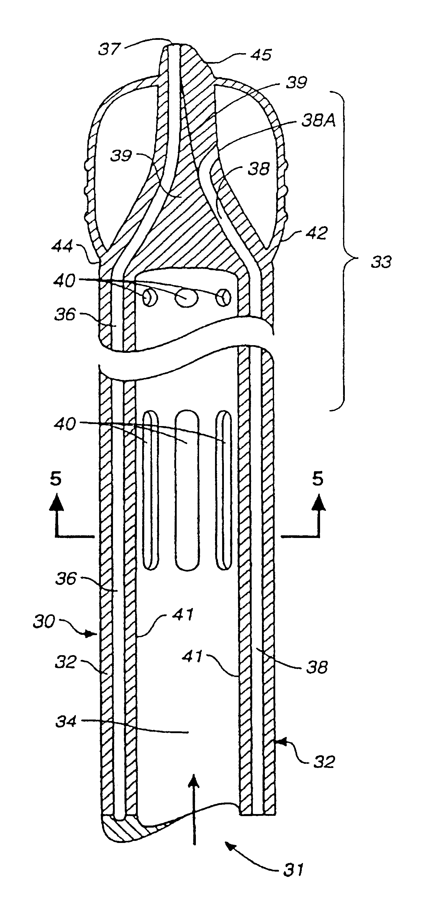
This Example shows the importance of the second and third channels, i.e., smaller channels 36 and 38 in the Figures, in the multichannel catheter bearing integrated into the wall of the larger channel and the importance of a significant outflow capacity in the outlet ports to minimize the pressure drop as the flow rate increases through the large channel.

In this test 3 / 8" inside diameter PVC tubing was used as a channel for standard saline solution. The flow rate through the various tubes was varied from 0.5 to 6 liters per minute. The saline was pumped from a first canister to a second using a roller pump. Tubes 1-6 having slightly different designs were used in the test as follows:

Tube #1: This had two tubes of a much smaller outside diameter, i.e., about 1 / 8" and about 1 / 32") within the length of large passageway that were not integrate dinto the wall of the 3 / 8" tube. It had 3 circular outlets of about 2 mm diameter at its distal end adjacent the balloon.

Tube #2: This was simila...


PUM


Abstract

This invention is a single, multichannel catheter useful for extracorporeal circulation of blood to a patient undergoing cardiovascular treatments or surgery. The catheter has three independent channels and an expandable balloon at one end of the catheter. The first channel (34) is the largest and is of a size that allows for delivery of blood to a patient in an amount sufficient to maintain the patient's metabolism and perfusion throughout the treatment or surgery. A second channel (36), smaller than the first, is integrated into the wall of the first channel, and is suitable for delivering a biologically active fluid (e.g., for cardioplegia) to the heart and / or venting the left heart. A third channel (38), also smaller than the first, is integrated into the wall of the first channel, and suitable for delivering a fluid to the balloon for its expansion when positioned in the ascending aorta to occlude the flow of blood to the heart. It is important that the first channel accounts for at least about 70% of the total channel volume. The catheter provides an improved means of performing cardiovascular surgery on a patient using a cardiopulmonary machine for extracorporeal circulation of blood. The catheter is particularly useful for cardiac surgery. The multichannel catheter is best prepared using an extrusion molding technique.

Description

This invention relates to a multichannel catheter for use in conjunction with cardiovascular examinations, treatments and surgery. It also relates to methods for making and using such a catheter.To better understand the background and problems faced by those of skill in this area of technology it is useful to understand the basic workings of the heart and circulatory system. The following discussion refers to schematics of the heart shown in FIGS. 1 and 2.The human heart is a muscular pump having four separate cavities and a series of valves allowing blood to pass in one direction only. Mammals, including humans, have a double circulatory system. Blood that has released oxygen to the tissues (9 and 14) and has absorbed carbon dioxide from them (venous blood) is returned to the heart through the superior and the inferior venae cavae (11 and 10). This blood enters the right auricle (3), whose contractions cause the blood to pass through the tricuspid valve (16) in the right ventricle ...

Claims


Application Information

Patent Timeline
Patent Type & Authority Patents(United States)
IPC IPC(8): A61B17/28A61B19/00A61M25/10A61B17/02A61B1/313A61B17/32A61B17/80A61B17/68A61B19/08A61B1/05A61M1/36A61M25/00A61B17/00A61B17/04A61M29/02A61F2/958
CPCA61M1/3659A61B17/0206A61B17/29A61B19/52A61M25/10A61B1/313A61B1/05A61B17/00234A61B17/2812A61B17/320016A61B17/8085A61B19/081A61B19/26A61B19/5225A61B2017/00199A61B2017/00243A61B2017/0046A61B2017/00557A61B2017/2904A61B2017/2905A61B2017/2946A61M25/0029A61M25/0032A61M25/1027A61M25/1034A61M25/1036A61M2025/0031A61M2025/1052A61M2025/1086A61M2025/1097A61M2210/127A61B90/36A61B90/50A61B46/10A61B90/37A61M1/3623
Inventor BERTOLERO, ARTHUR A.BERTOLERO, RAYMOND S.RIEBMAN, JEROME B.
Owner SORIN GRP USA INC
Why Eureka
Try Eureka