Non-involute gears with conformal contact

a conformal contact, non-volute technology, applied in the direction of gearing elements, belts/chains/gears, hoisting equipments, etc., can solve the problems of low efficiency or durability of relative crude power transmission systems, inability to make good use of these advantages, and low cycloid profile. achieve the effect of removing high contact pressure peaks

Inactive Publication Date: 2005-01-04
HAWKINS RICHARD M
View PDF22 Cites 34 Cited by
  • Summary
  • Abstract
  • Description
  • Claims
  • Application Information

AI Technical Summary

Benefits of technology

The present invention comprises a modification to otherwise conventional gear tooth profiles, serving to eliminate high contact pressure peaks between mating gear teeth during gea

Problems solved by technology

It was recognized that such relatively crude power transmission systems were not particularly efficient or durable, but it was not until metallurgy and machining was better developed that more efficient gear systems were developed.
Such a cycloidal (i. e., non-involute) profile possesses a number of advantages over the involute shape, but it was generally not possible to make beneficial use of these advantages until modern times and the development of more sophisticated machining technology.
Nonetheless, the cycloid profile has not found great favor for the various reasons noted above, even though at least some of those reasons are no longer valid with modern machining technology.
This results in the bending stresses on each tooth being relatively low for a given torque being applied from the driving to the driven gear.
However, the Wilkin gears, due to their relative length and multiple tooth engagement, result in considerable sliding contact between teeth in the approach and departure areas of mesh.
Also, while Wilkin configures his gear teeth with relatively wider addendum portions in order to provide the desired multiple tooth engagement, he does not provide any form of relief in these convex areas to preclude high compressive forces between the end of one tooth and the convex addendum area of the adjacent tooth.
The Rivin coating does not provide a relief in the tooth profile to relieve contact pressure between mating convex areas of the gear teeth.
This results in non-conformal contact across the entire tooth face, with resulting relatively high contact pressures.
However, Drago does not provide any means for relieving the profile to relieve such high contact pressures, as provided by the present invention.
Such a gear can be used to drive another gear by means of t

Method used


Image

  • Non-involute gears with conformal contact
  • Non-involute gears with conformal contact
  • Non-involute gears with conformal contact

Examples


Embodiment Construction

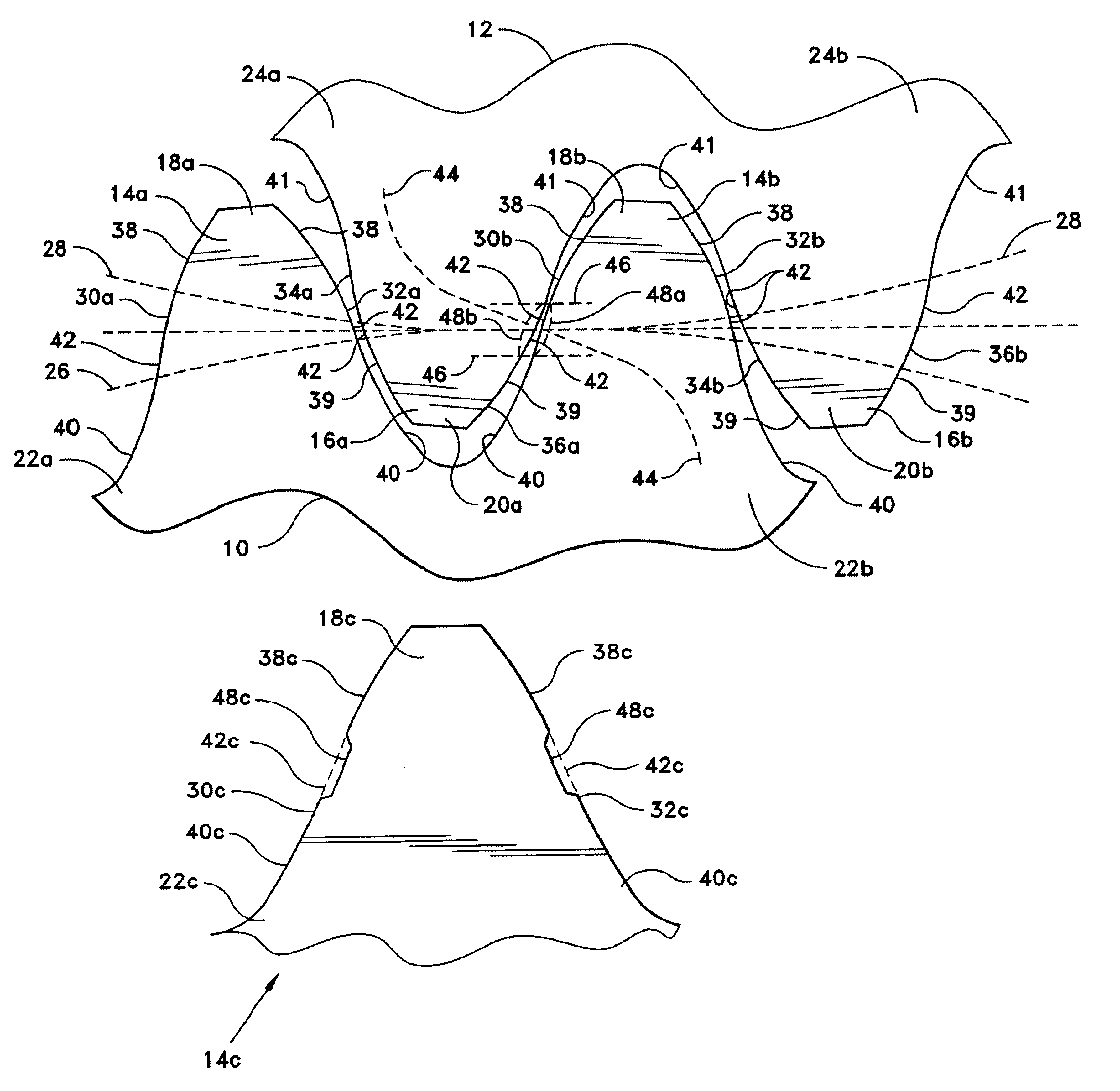
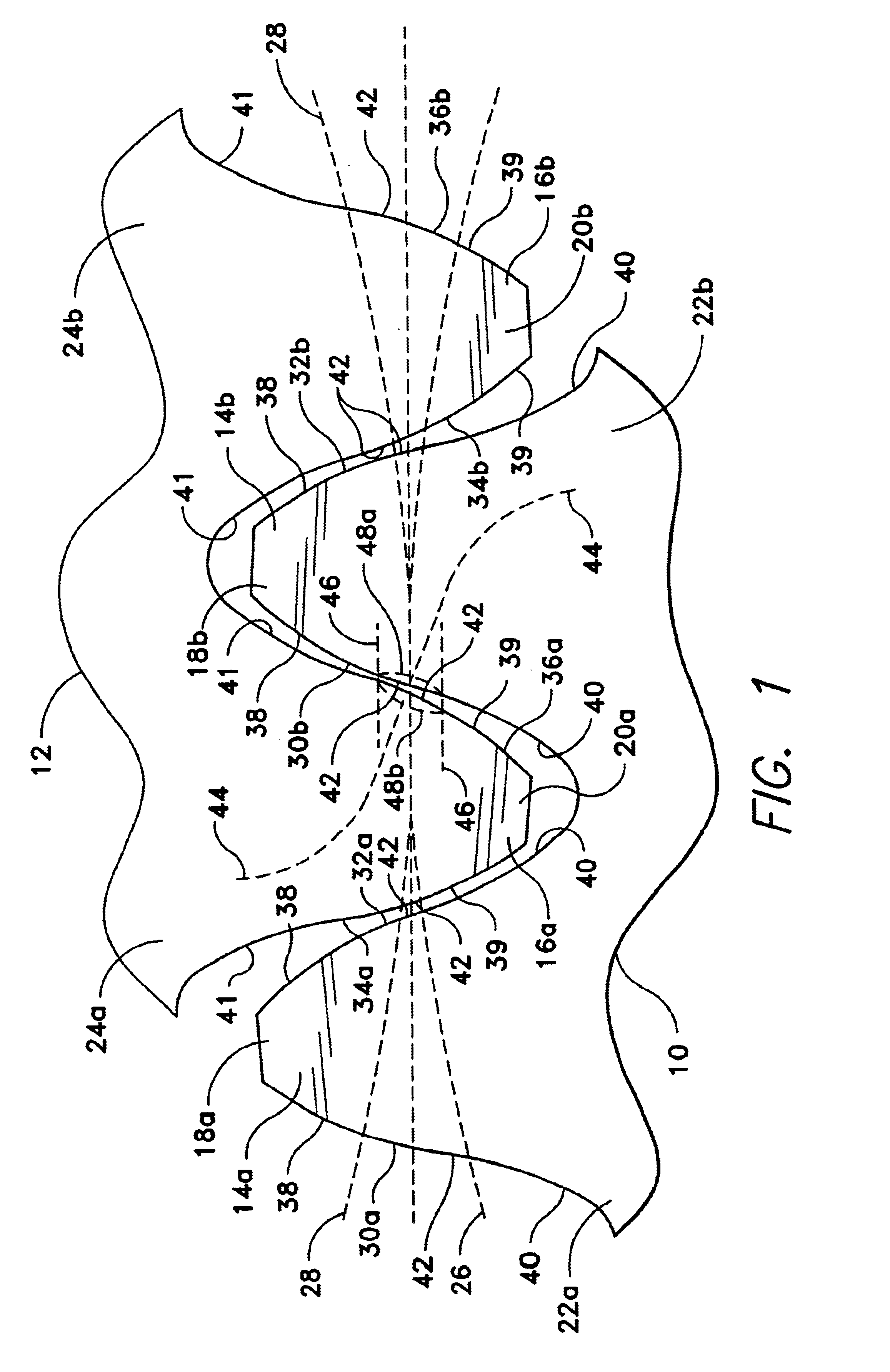
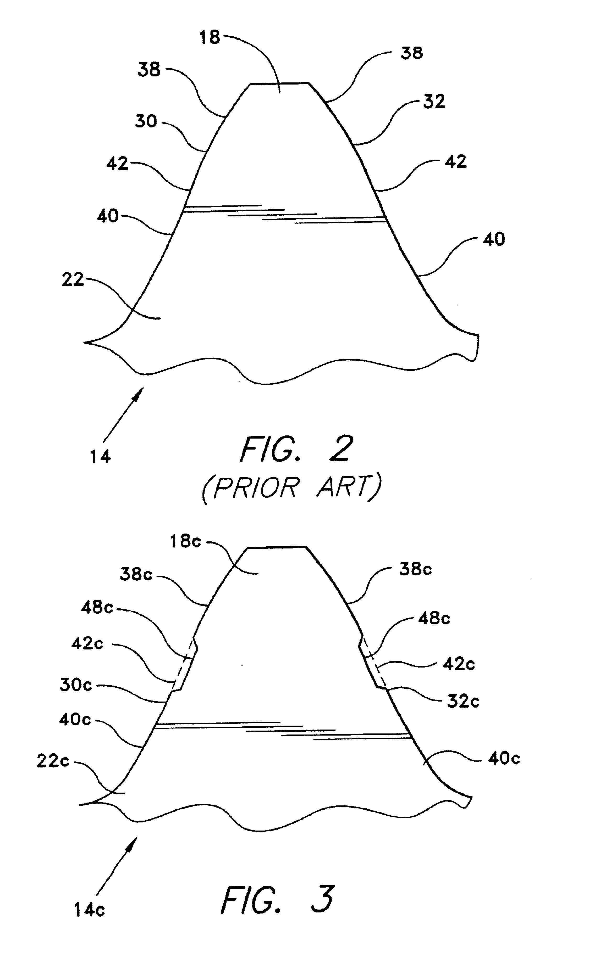
The present invention comprises various embodiments of gear tooth profiles, shapes, or patterns each including means for greatly reducing or eliminating extremely high contact pressures between mutually convex surfaces of mating gear teeth. This is achieved by forming a relief or depression in the face of at least one of the two mating teeth, thereby precluding contact between the two teeth at that location. While the present invention is directed primarily to use with non-involute (e. g., cycloid) gear tooth profiles, it will be seen that it may be adapted to virtually any form of gear profile in which an area of non-conformal contact (i. e., where the tooth profiles result in a line of contact across the teeth, rather than an area of mutually congruent contact) would otherwise occur.

FIG. 1 illustrates the principle of the present invention as applied to the gear teeth of two meshed gears 10 and 12. While FIG. 1 illustrates only a portion of each of the two gears 10 and 12, it will...


PUM


Abstract

Several embodiments of various non-involute gear tooth profiles incorporate relief areas formed across the area of the tooth face generally symmetrically to each side of the pitch circle of the gear. The relief area serves to preclude contact across the areas of meshing or mating gear teeth where convex-to-convex contact would otherwise occur, thus precluding high pressure contact between the two gear teeth at the area of the relief. The remainder of the contact of such non-involute gear tooth profiles provides conformal contact, i. e., convex-to-concave mating faces with correspondingly low pressures developed between the tooth portions. The present invention enables a given gear set to absorb considerably greater torque and force than would otherwise be they case, or alternatively allows gear sets to be made considerably smaller and lighter for a given torque transmission, than would otherwise be the case.

Description

BACKGROUND OF THE INVENTION1. Field of the InventionThe present invention relates generally to gear tooth configurations, and more specifically to various gear tooth profiles having a non-involute shape to provide conformal contact between adjacent teeth. The present invention relieves the compressive forces between convex to convex contact of mating gear teeth, by means of a relief formed in one or both of the faces off the mating teeth.2. Description of the Related ArtPower transmission through gears and / or racks, was first developed hundreds of years ago with simple wooden dowel and socket devices. It was recognized that such relatively crude power transmission systems were not particularly efficient or durable, but it was not until metallurgy and machining was better developed that more efficient gear systems were developed.It was soon recognized that the specific shape or profile of the teeth of gears, has a considerable bearing upon the accuracy of movement of the gear train, ...

Claims


Application Information

Patent Timeline
IPC IPC(8): F16H55/08F16H55/02
CPCF16H55/08Y10T74/19949Y10T74/19972Y10T74/19958
Inventor HAWKINS, RICHARD M.
Owner HAWKINS RICHARD M
Why Eureka
Try Eureka