Wafer edge cleaning utilizing polish pad material

a technology of polish pad and wafer edge, applied in carpet cleaners, instruments, photosensitive materials, etc., can solve problems such as re-deposition of contaminants

Inactive Publication Date: 2005-01-04
GLOBALFOUNDRIES INC
View PDF12 Cites 40 Cited by
  • Summary
  • Abstract
  • Description
  • Claims
  • Application Information

AI Technical Summary

Benefits of technology

There is disclosed in accordance with another aspect of the invention an improvement in a brush cleaning apparatus for cleaning a major surface of a wafer and including wafer guide wheels for transporting the wafer. The improvement includes a polish pad material disposed on a circumference of the guide wheels. The polish pad material is a material used in chemical-mechanical polishing of the wafer. The polish pad material contacts an edge portion of the wafer during cleaning thereof, thereby removing contaminants from the edge portion of the wafer, so that edge cleaning is performed in situ in addition to the brush cleaning of the major surface of the wafer.

Problems solved by technology

These contaminants can later harden and crumble back on to the wafer resulting in the contaminants being redeposited.

Method used


Image

  • Wafer edge cleaning utilizing polish pad material
  • Wafer edge cleaning utilizing polish pad material
  • Wafer edge cleaning utilizing polish pad material

Examples


second embodiment

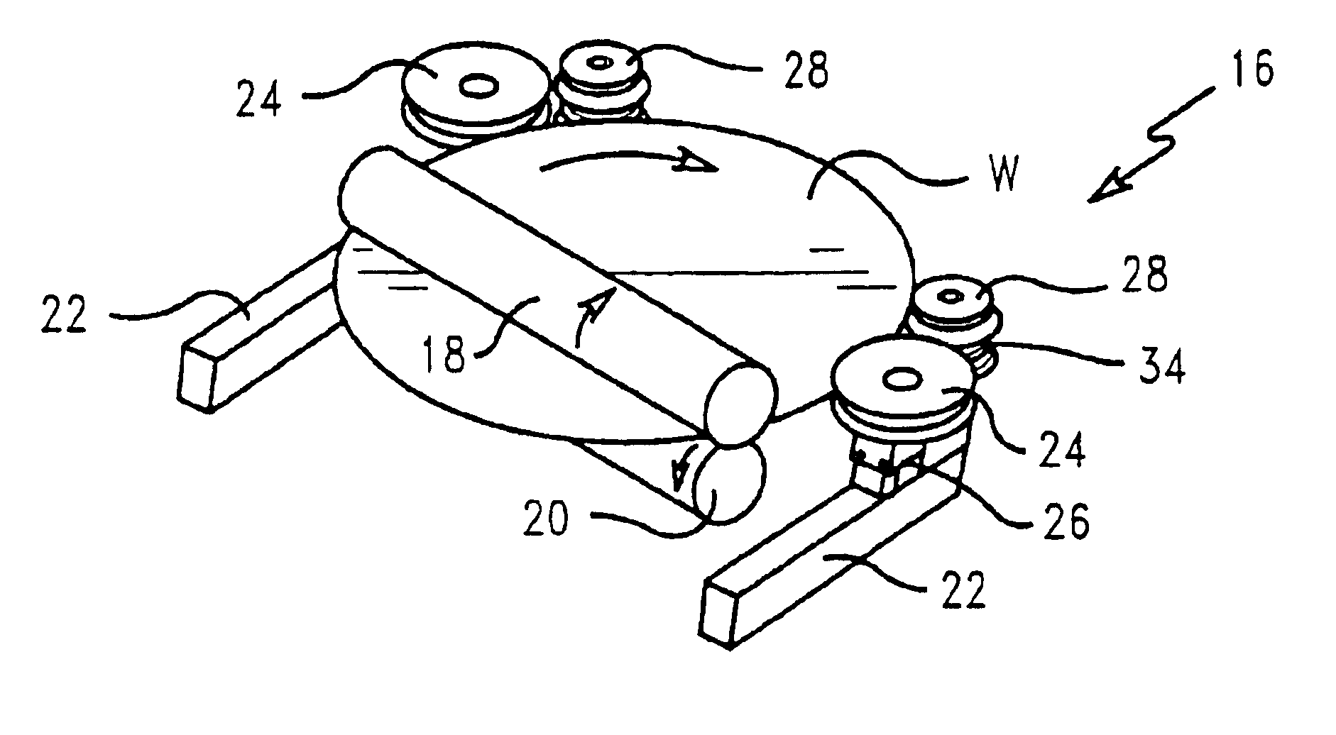
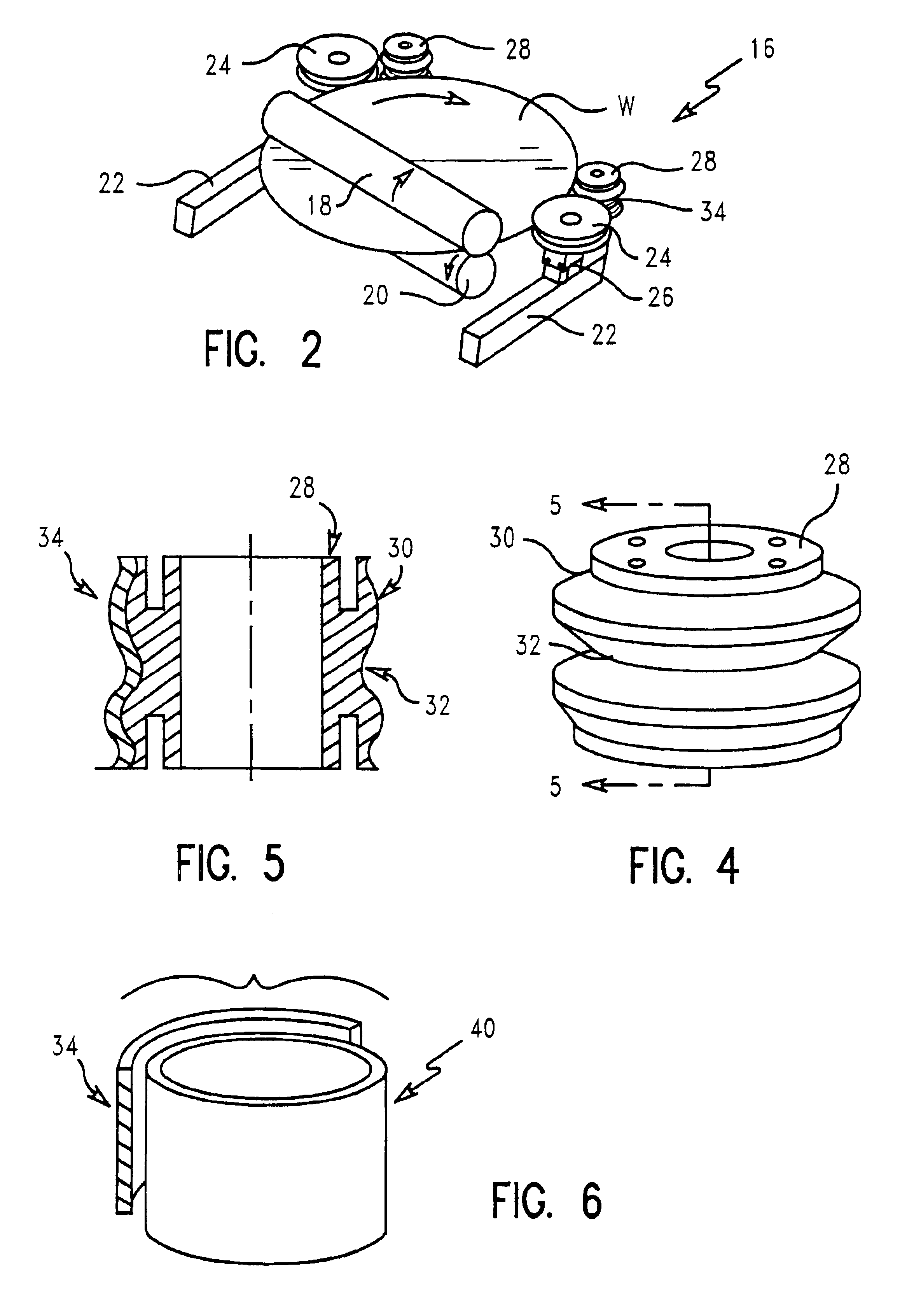
Referring to FIG. 7, a cleaning apparatus 16′ in accordance with the invention is illustrated. The cleaning apparatus 16′ includes the control arms 22 and drive wheels 24, similar to the embodiment of FIG. 2. An applicator 42 is positioned to contact an edge of the wafer W. In the illustrated embodiment of the invention, the applicator 42 comprises a roll applicator, such as a deodorant roll applicator, where a contact ball 44 spins with rotation of the wafer W. The ball is housed in a cylindrical housing 46 which stores a supply of a cleaner. The cleaner is applied to the edge of the wafer W in contact with the ball 44, as is known. The cleaner may comprise, for example, dilute hydrofluoric acid (DHF).

The applicator 42 allows a small volume of DHF to be applied to the area to be cleaned, namely the edge of the wafer W. Alternatively, the DHF applicator 42 may be of a sponge type where the contact is provided by a PVA sponge or other compatible sponge material that allows a small am...

third embodiment

Referring to FIG. 8, a cleaning apparatus 16″ in accordance with the invention is illustrated. This embodiment includes the control arms 22, drive wheels 24 and guide wheels 28 as in FIG. 3. Additionally, a brush cleaner 52 can be shuttled into and out of position relative to an edge of the wafer W using a pneumatic cylinder 54 or the like. The brush 52 can be of cup shape made of nylon or other non-scratching material to silicon. The brush 52 can also be a standard straight bristle type brush or any other configuration. Likewise, the brush may be an ultrasonic type or rotary type which provides additional cleaning action to the wafer's edge. In the illustrated embodiment of the invention, the brush 52 comprises a cup brush and a rotary motion is used, as illustrated in FIG. 9, to remove contaminants from the wafer's edge. A rotary speed of up to 100 rpm may be applied. The rotary motion can be supplied by a DC motor via a drive cable or other means known in the art. The brush 52 ma...


PUM

PropertyMeasurementUnit
acidaaaaaaaaaa
circumferenceaaaaaaaaaa
forceaaaaaaaaaa

Abstract

An improvement is disclosed in a brush cleaning apparatus for cleaning a major surface of a wafer and including wafer guide wheels for transporting the wafer. The improvement includes a polish pad material disposed on a circumference of the guide wheels. The polish pad material is a material used in chemical-mechanical polishing of the wafer. The polish pad material contacts an edge portion of the wafer during cleaning thereof, thereby removing contaminants from the edge portion of the wafer, so that edge cleaning is performed in situ in addition to the brush cleaning of the major surface of the wafer.

Description

FIELD OF THE INVENTIONThis invention relates to cleaning of semiconductor wafers and, more particularly, to an apparatus and method for wafer edge cleaning using a polish pad material such as is used in a chemical-mechanical polishing apparatus.BACKGROUND OF THE INVENTIONChemical-mechanical polishing (CMP) is performed in the processing of semiconductor wafers and / or chips on commercially available polishing apparatus. The standard CMP polishing apparatus has a circular polishing pad and a rotating carrier for holding the wafer. A slurry is used on the polishing pad.The semiconductor wafer undergoes a cleaning process subsequent to the CMP process. The cleaning process is necessary to prevent redeposition of foreign matter on the wafer and subsequent process operations, which inflicts yield detractors and loss of chips per wafer.One conventional cleaning process comprises a brush cleaner. The semiconductor wafer is rotated by drive wheels while two brushes, or sets of brushes, one o...

Claims


Application Information

Patent Timeline
Patent Type & Authority Patents(United States)
IPC IPC(8): A46B13/00A46B13/04B08B1/04B24B1/00B24B9/06H01L21/00H01L21/306
CPCB08B1/04H01L21/67046H01L21/02052B24B9/065
Inventor ZIEMINS, ULDIS A.DELEHANTY, DONALD J.KHOURY, RAYMOND M.OCASIO, JOSE M.
Owner GLOBALFOUNDRIES INC
Why Eureka
Try Eureka