

Lithographic projection apparatus and particle barrier for use therein
- Summary
- Abstract
- Description
- Claims
- Application Information
AI Technical Summary
Benefits of technology
Problems solved by technology
Method used
Image

Examples
Embodiment Construction
ention will now be described, by way of example only, with reference to the accompanying schematic drawings in which corresponding reference symbols indicate corresponding parts, and in which:
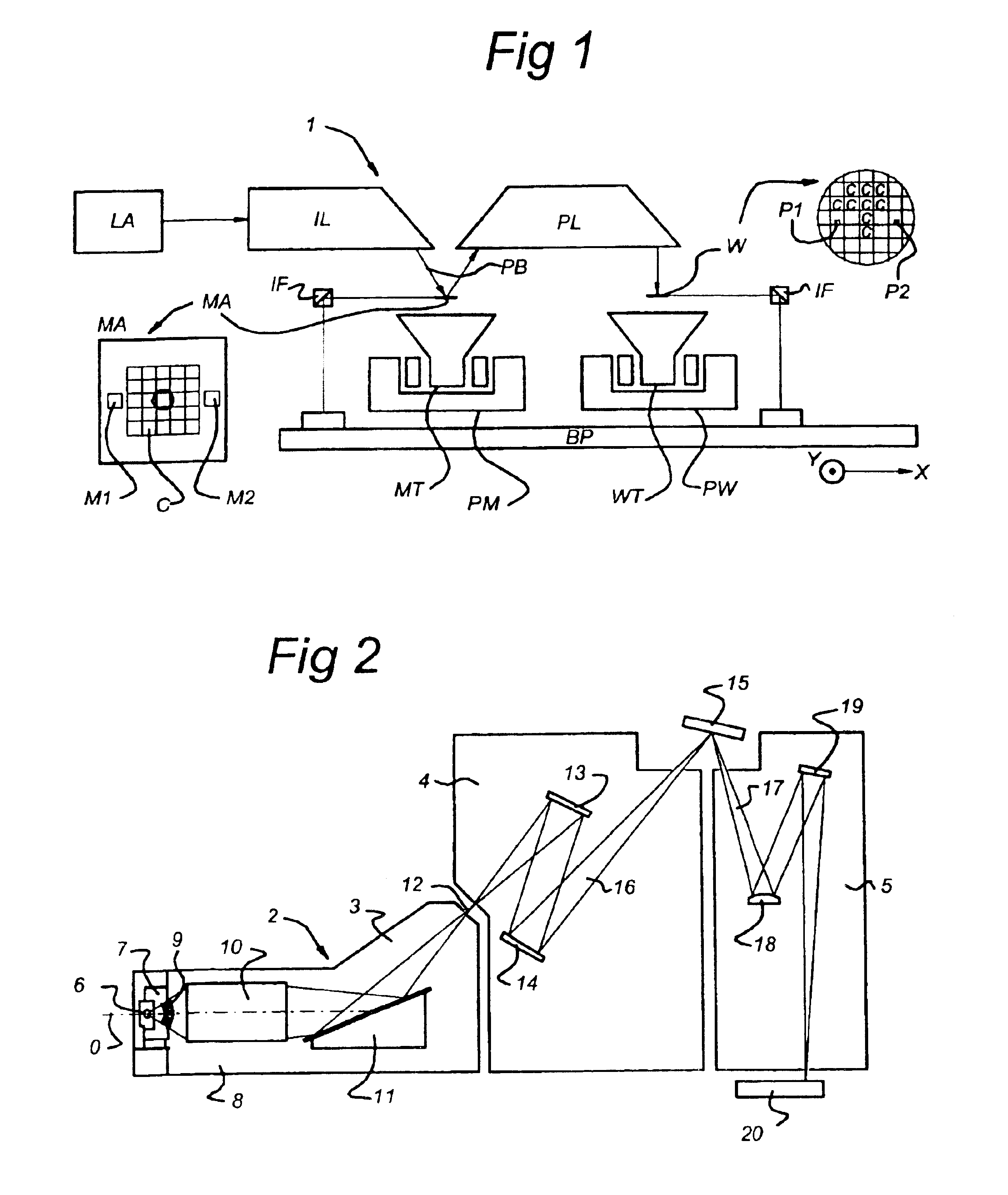
[0028]FIG. 1 schematically depicts a lithographic projection apparatus according to an embodiment of the present invention;
[0029]FIG. 2 shows a side view of an EUV illuminating system and projection optics of a lithographic projection apparatus according to the present invention;
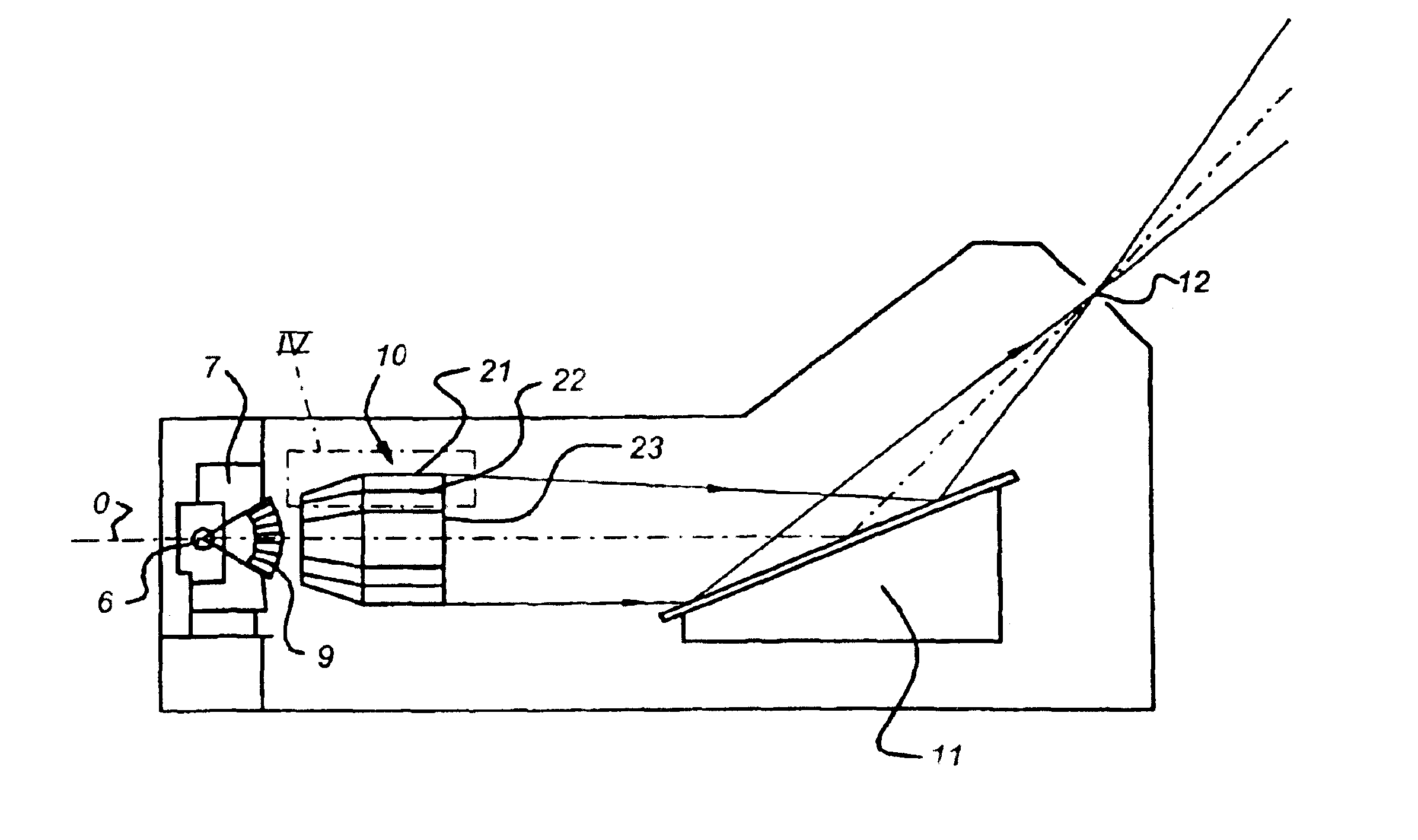
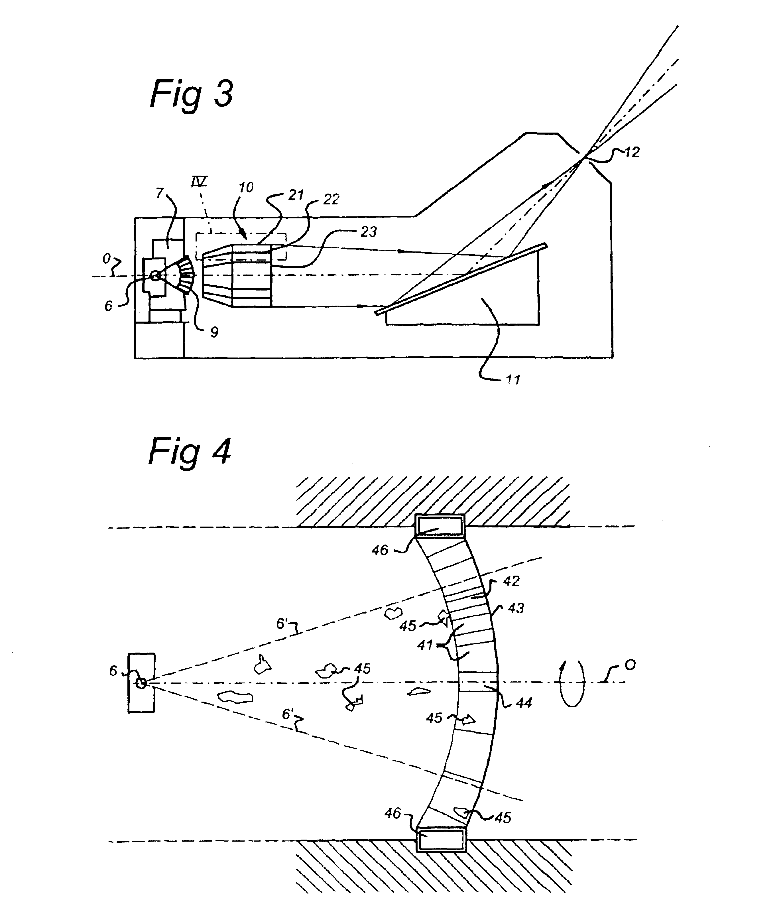
[0030]FIG. 3 shows a detail of the radiation source and grazing incidence collector of the present invention;
[0031]FIG. 4 shows in a cross-section a schematic drawing of the rotating particle barrier according to the present invention; and
[0032]FIG. 5 shows in a cross-section a schematic drawing of two contra-rotating particle barriers according to the present invention.
DETAILED DESCRIPTION
[0033]FIG. 1 schematically depicts a lithographic projection apparatus 1 according to an embodiment of the invention. The apparatus ...
PUM
 Abstract
Description
Claims
Application Information