Ion beam apparatus, ion beam processing method and sample holder member

a technology of ion beam and ion beam processing, which is applied in the direction of electrical apparatus, preparing samples for investigation, and discharge tubes, etc., can solve the problems of damage to the section, inability to carry out tem observation in a satisfactory manner, and adamant layer, so as to suppress the re-attachment of secondary particles

Inactive Publication Date: 2005-01-04
HITACHI HIGH TECH SCI CORP
View PDF1 Cites 33 Cited by
  • Summary
  • Abstract
  • Description
  • Claims
  • Application Information

AI Technical Summary

Benefits of technology

is to solve the above described problems, and to provide an ion beam device, and ion beam processing method, and a holder member, capable of suppressing re-attachment of secondary particles to the section in a straightforward manner.

Problems solved by technology

If the unwanted damage layer 203 is formed on the surface to be observed in this way, the damage layer proves a hindrance and it is not possible to carry out TEM observation in a satisfactory manner.
There is also damage to the section caused by the gas ion beam irradiation, but only to a small extent.
As described above, in the case of slicing processing using a FIB, since it is possible to have a damage layer on the processed section, there is a problem in that it is not possible to carry out favorable section observation using a TEM or SEM etc.
By removing the damage layer after section processing with the FIB using the gas ion beam, the above described problem is solved, but in this case, a problem arises with regard to re-attachment of secondary particles, as will be described in the following.
However, in this case there is the following problem.
Since the Ar ion beam is a beam that can not be sufficiently focused, it is not possible to carry out setting so that the two side walls and bottom surface are not irradiated.
In addition, in preventing the Ar ion beam from irradiating the bottom surface, the direction and positional relationship of the Ar ion beam with respect to the sample must be set with high precision, and this kind of setting takes time.

Method used


Image

  • Ion beam apparatus, ion beam processing method and sample holder member
  • Ion beam apparatus, ion beam processing method and sample holder member
  • Ion beam apparatus, ion beam processing method and sample holder member

Examples


modified example 1

(Modified Example 1 of Sample Holder)

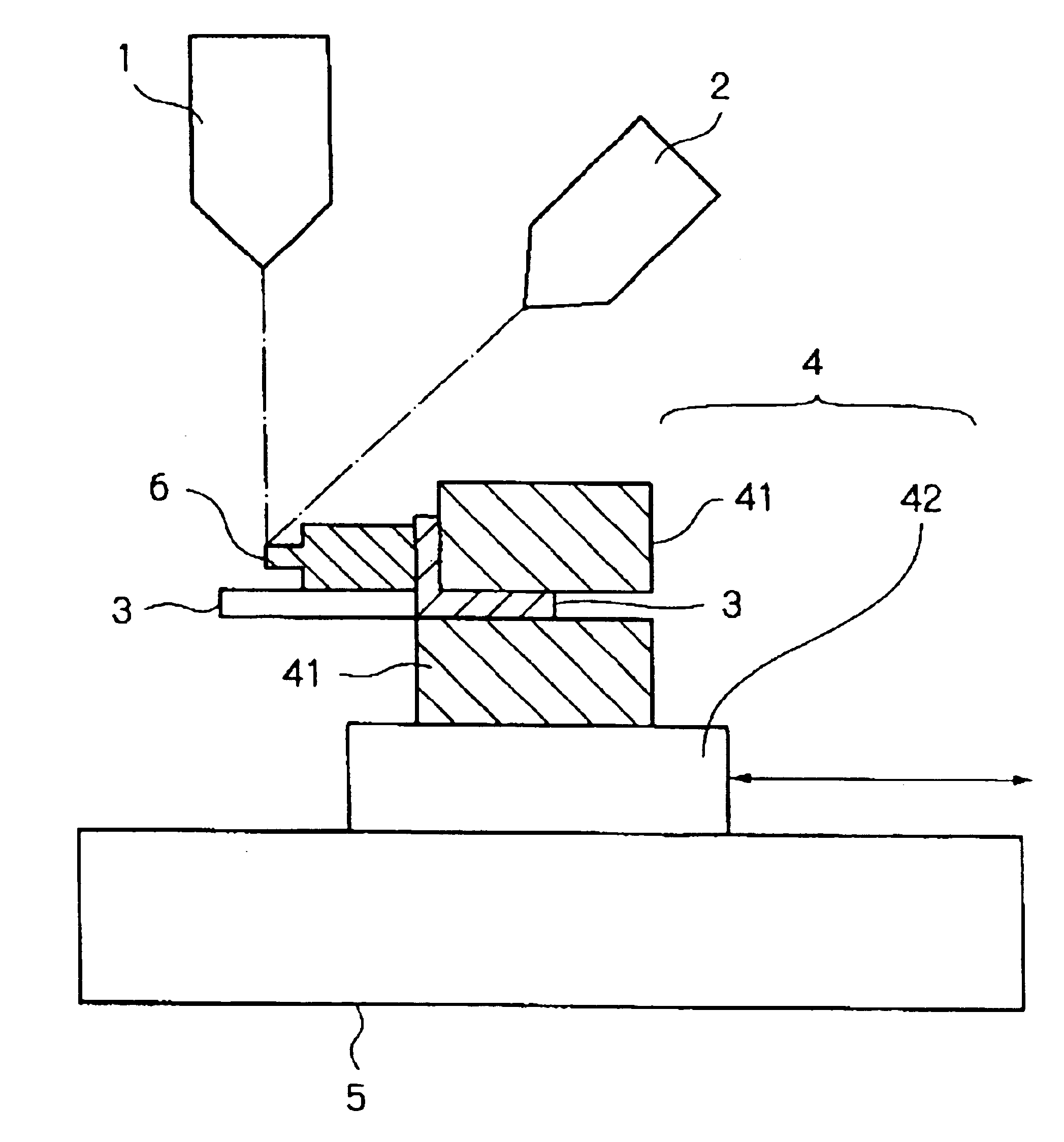
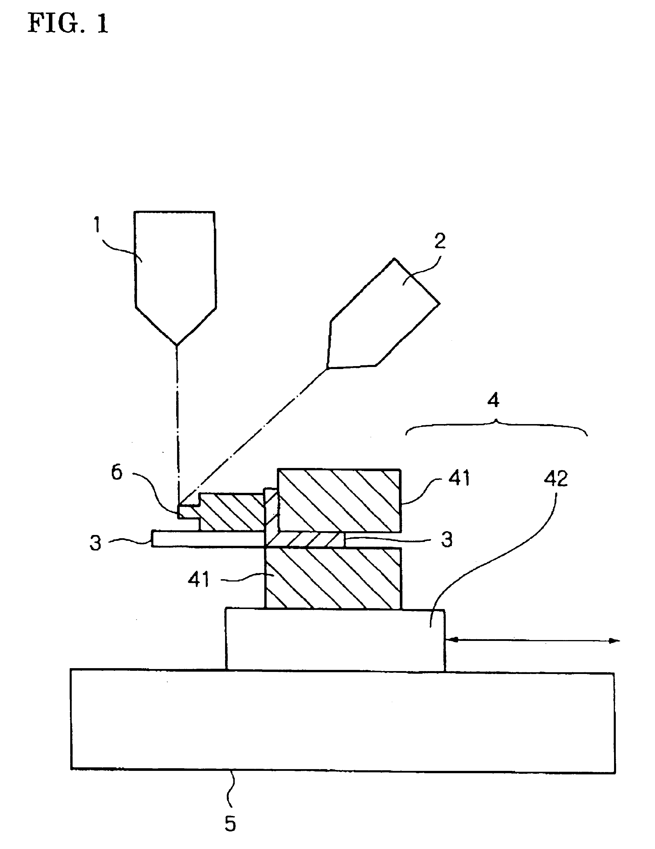
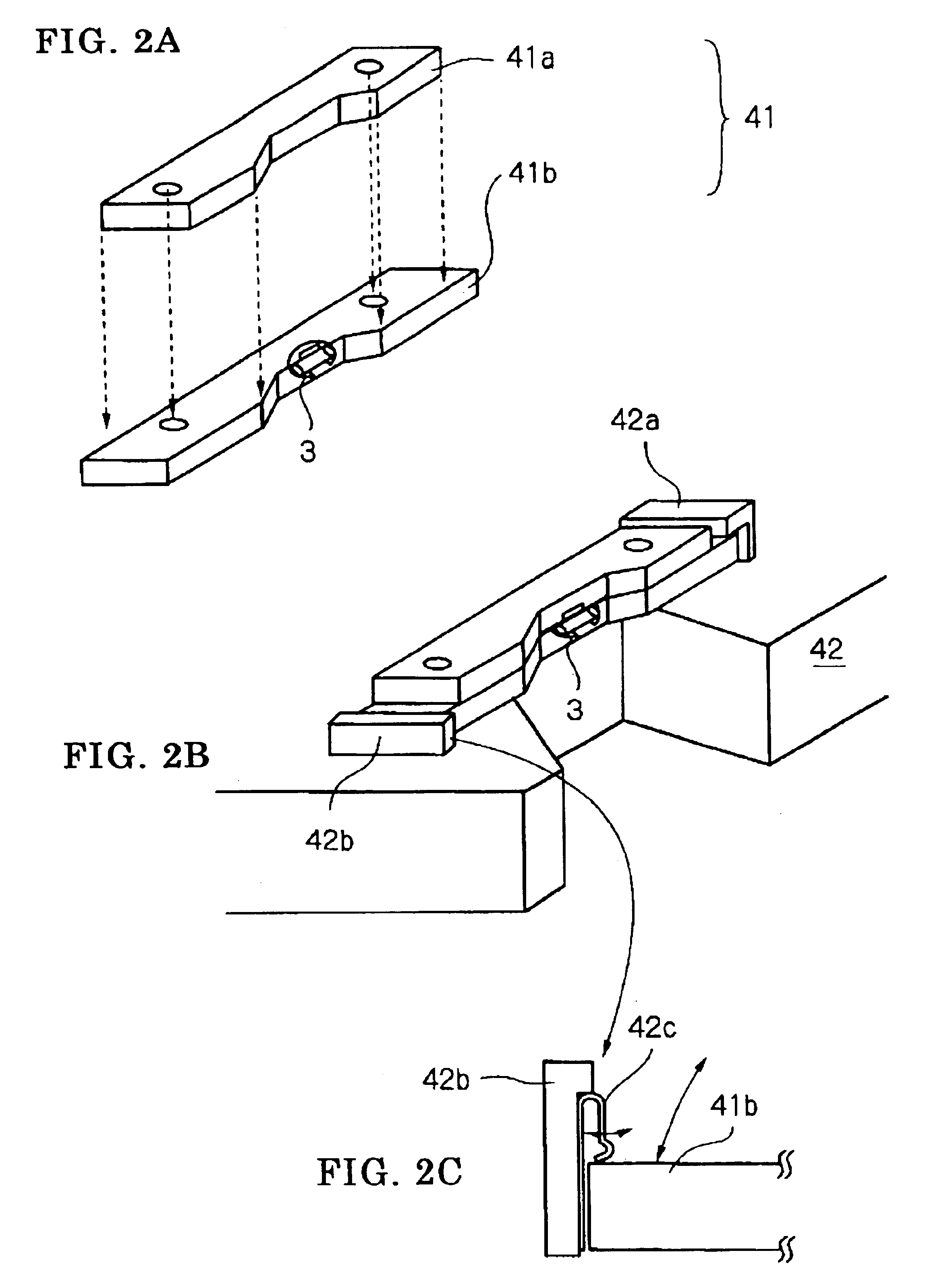
A modified example of a clamp section of the sample holder uses in the ion beam device of the present invention is shown in FIG. 4. This clamp section is made up of a press contact section 51, a receive section 52, support struts 53a and 53b, and a platform 54. The press contact section 51 and the receive section 52 clamp the sample holding member 3. This is almost the same as the structure shown in FIG. 9(d). The two ends 52a and 52b of the receive section 52 are fixed to the platform 54 through the respective support struts 53a and 53b. The platform 54 is fixed to the fixing platform 42 shown in FIG. 2, for example, by bringing one end into contact with an abutment section 42a, and fitting the other end into the fixing section 42b.

The platform 54 is fixed to the fixing platform 42, and a surface of a sample 6 held on the sample holding member 3 is positioned at a fixed surface side of the fixing platform 42. According to this structure, the ga...

modified example 2

(Modified Example 2 of Sample Holder)

Another modified example of a sample holder used in the ion beam device of the present invention is shown in FIG. 6. This sample holder has a clamp section 61 for clamping a sample holding member 3 holding a sample 6, and a fixing platform 62 to which the clamp section 61 is fixed.

The fixing platform 62 is provided with a fixed surface 62a arranged so that an angle formed with the gas ion beam irradiated to the section of the sample 6 at a specified incident angle is substantially equal to that specified incident angle. The clamp section 61 is fixed to the fixing platform 62 capable of rotation about a shaft 63 parallel to the fixed surface 62a. According to this structure, after removing a damage layer of one section of the sample 6, it is possible to rotate the clamp section 61 through 180° around the shaft 53 to remove a damage layer of another section of the sample 6. As a result, the sample 6 does not need to be removed, and processing time ...


PUM

PropertyMeasurementUnit
thicknessaaaaaaaaaa
thicknessaaaaaaaaaa
acceleration voltageaaaaaaaaaa

Abstract

An ion beam processing device has a sample holder for fixing a sample on which a section has been formed by irradiation of a specified focused ion beam from a surface side, and gas ion beam irradiation device for irradiating a gas ion beam to a region of the sample fixing using the holder member that contains the section to remove a damage layer on the section. The gas ion beam from the gas ion beam irradiation device irradiates the section from a rear surface side of the sample at a specified incident angle.

Description

BACKGROUND OF THE INVENTIONThe present invention relates to an ion beam device and ion beam processing method for carrying out section processing by irradiating an ion beam to a specified part of a sample, and also to a holder member for fixing the sample.As an ion beam device, a focused ion beam device and an ion milling device are known. These devices are used in sample manufacture when carrying out section observation of fault locations of a wafer using a TEM (Transmission Electron Microscope), for example. In particular, since an FIB device scans a sample surface with a sufficiently focused ion beam and can perform accurate section processing of specific sites such as defects while detecting secondary electrons generated at the time of scanning and observing as an image, FIB devices are widely used as evaluation devices for semiconductor manufacturing processes. Recently, combination type ion beam devices that combine FIB devices and observation devices such as scanning electron...

Claims


Application Information

Patent Timeline
Patent Type & Authority Patents(United States)
IPC IPC(8): G01N1/28G01N1/32H01J37/31H01J37/26H01J37/317H01J37/305
CPCG01N1/32H01J37/3056H01J2237/31749H01J2237/20214H01J2237/31745H01J2237/2007
Inventor KODAMA, TOSHIOHASUDA, MASAKATSUFUJII, TOSHIAKIIWASAKI, KOUJISUGIYAMA, YASUHIKOTAKAGI, YASUYUKI
Owner HITACHI HIGH TECH SCI CORP
Why Eureka
Try Eureka