Ion beam processing apparatus

a technology of processing apparatus and ion beam, which is applied in the field of electronic parts manufacturing technology, can solve the problems of larger beam diameter, achieve the effects of improving yield, shortening time, and improving precision in section processing

Inactive Publication Date: 2008-03-27
HITACHI HIGH-TECH CORP
View PDF13 Cites 24 Cited by
  • Summary
  • Abstract
  • Description
  • Claims
  • Application Information

AI Technical Summary

Benefits of technology

[0019]According to the present invention, an ion beam processing technology for improving the precision in processing of a section of a sample to be performed using an ion beam without making a processing time longer than a conventional pro...

Problems solved by technology

However, since aberrations caused by a len...

Method used


Image

  • Ion beam processing apparatus
  • Ion beam processing apparatus
  • Ion beam processing apparatus

Examples


first embodiment

[0038]The present embodiment will be described on the assumption that an ion source is tilted relative to an ion beam column and a stencil mask is used to mold an ion beam.

[0039]Now, an ion source shall be a plasma ion source that draws out an ion beam of inert gas or a gas element such as oxygen or nitrogen. If inert gas or an element species such as oxygen or nitrogen is selected as an ion species for the ion source, the electric characteristics of a device will not be affected at all. Therefore, after processing is completed using an ion beam, if a processed wafer is returned to a production line, a defective will hardly be produced. In such inline application, a very small amount of metal impurity is produced in the plasma ion source. When the impurity reaches a sample, the sample may become defective, though it is rare. One of impurities is metal ions, and other impurity is metal neutral particles. Neutral particles cannot be controlled using a lens or an electrostatic deflecto...

second embodiment

[0106]The sample production apparatus in accordance with the first embodiment includes the first sample stage and the second sample stage on which a test piece extracted by performing ion-beam processing is mounted. The present embodiment will be described as an apparatus that does not always include the second sample stage but has a tilting ability to vary an angle of irradiation, at which an ion beam is irradiated to a sample, by rotating the first stage about the tilting axis of the first stage.

[0107]Moreover, in the first embodiment, an ion beam-irradiated sample point and an electron beam-irradiated sample point are deviated from the center of the sample mounting surface, and located at mutually different positions. In the apparatus of the present embodiment, the ion beam irradiation axis and electron beam irradiation axis intersects above a sample.

[0108]In the present apparatus, an axis along which an ion beam is drawn out of an ion source and an axis along which the ion beam ...

third embodiment

[0123]In the sample production apparatuses in accordance with the first and second embodiments respectively, neutral particles generated in the plasma ion source or neutral particles generated in the middle of the column will not reach a sample. However, ions of an impurity such as a metal generated in the plasma ion source reach the sample. The present embodiment will be described as a sample production apparatus in which a mass separator is disposed in the middle of a path of an ion beam in order to trap the impurity ions. Even in the present embodiment, a beam molded by passing through an opening in a stencil mask and projected on a sample is employed.

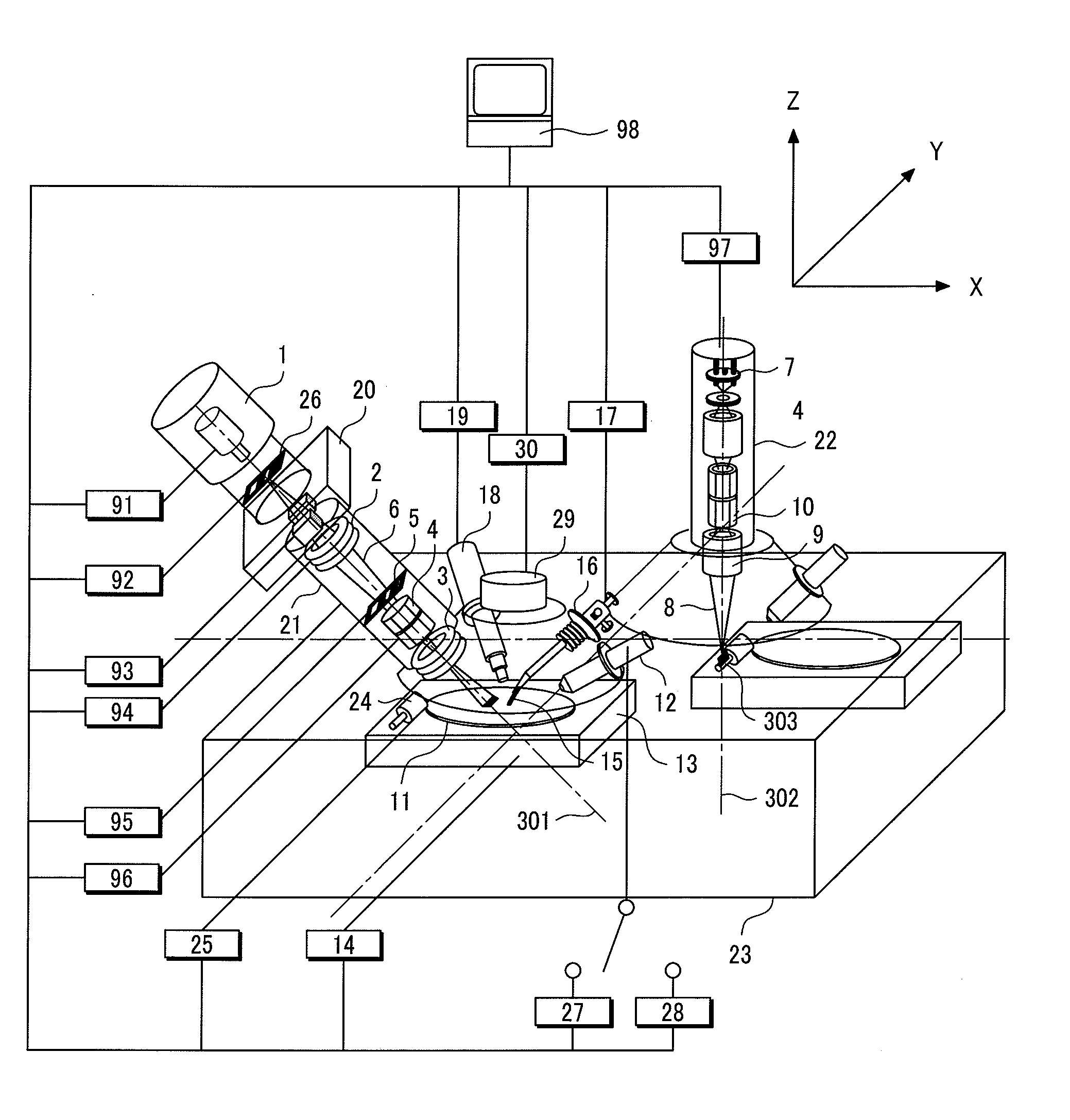
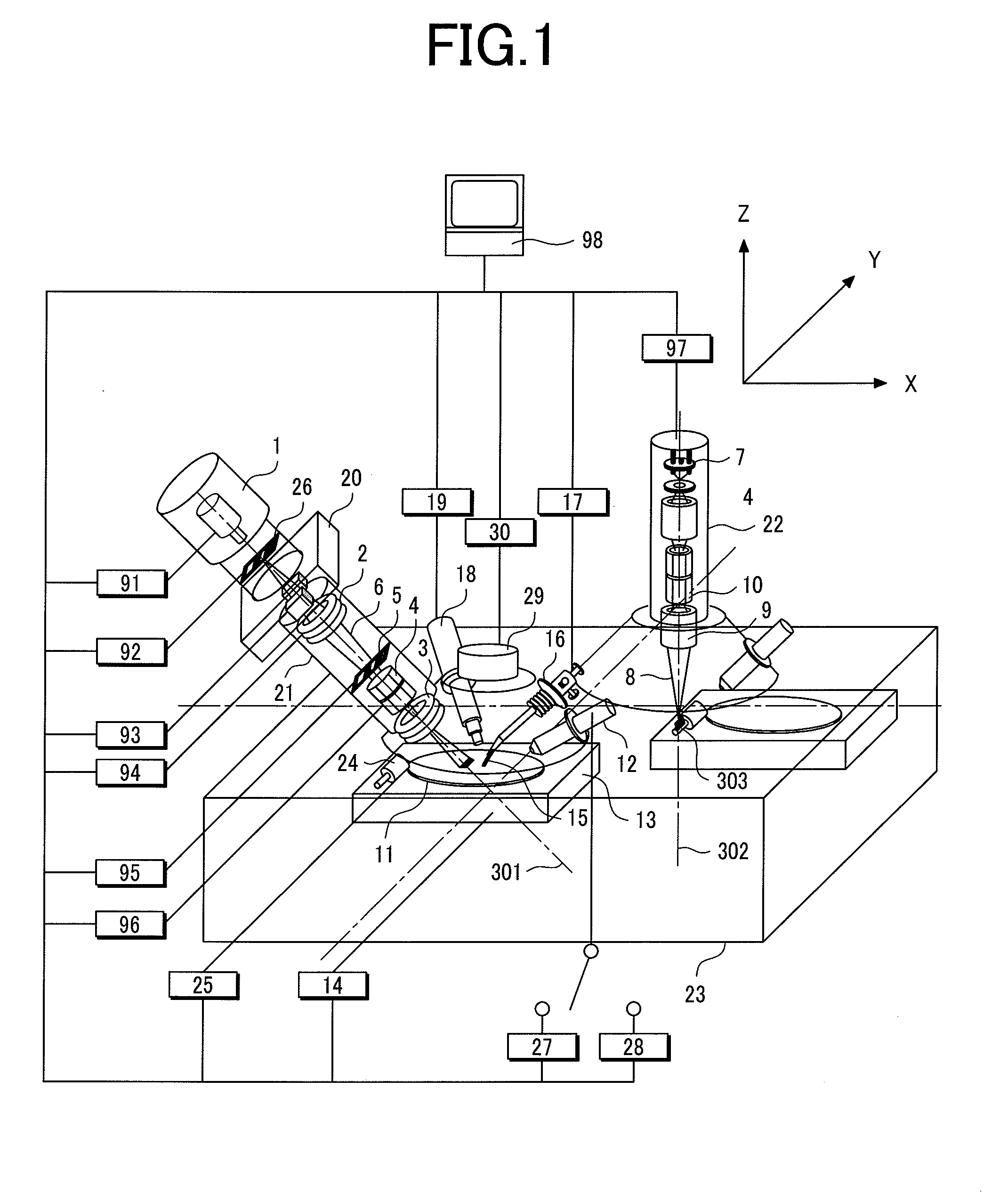
[0124]FIG. 14 shows the configuration of an ion beam processing apparatus in accordance with the third embodiment of the present invention. The ion beam processing apparatus includes an ion-beam irradiation optical system composed of a duoplasmatron 1 that releases ions of a gas such as argon, neon, xenon, krypton, oxygen, or nitrog...


PUM


Abstract

The present invention provides an ion beam processing technology for improving the precision in processing a section of a sample using an ion beam without making a processing time longer than a conventionally required processing time, and for shortening the time required for separating a micro test piece without breaking the sample or the time required for making preparations for the separation. An ion beam processing apparatus is structured so that an axis along which an ion beam is drawn out of an ion source and an ion beam irradiation axis along which the ion beam is irradiated to a sample mounted on a first sample stage will meet at an angle. Furthermore, the ion beam processing apparatus has a tilting ability to vary an angle of irradiation, at which the ion beam is irradiated to the sample, by rotating a second sample stage, on which a test piece extracted from the sample by performing ion beam processing is mounted, about the tilting axis of the second sample stage. The ion beam processing apparatus is structured so that a segment drawn by projecting the axis, along which the ion beam is drawn out of the ion source, on a plane perpendicular to the ion beam irradiation axis can be at least substantially parallel to a segment drawn by projecting the tilting axis of the second sample stage on the plane perpendicular to the ion beam irradiation axis.

Description

CLAIM OF PRIORITY[0001]The present invention claims priority from Japanese application JP 2006-072600 filed on Mar. 16, 2006, the content of which is hereby incorporated by reference on to this application.BACKGROUND OF THE INVENTION[0002]The present invention relates to a manufacturing technology for electronic parts such as semiconductor devices. More particularly, the present invention is concerned with an ion beam processing technology for processing a section of a sample with an ion beam, or for processing a sample so as to separate a micro test piece from the sample or make preparations for the separation.[0003]Manufacture of electronic parts such as semiconductor memories represented by a dynamic random access memory (DRAM), microprocessors, semiconductor devices including a semiconductor laser, and magnetic heads is requested to offer a high yield. This is because a decrease in the yield derived from production of a defective invites degradation of cost-effectiveness. Theref...

Claims


Application Information

Patent Timeline
IPC IPC(8): H01J37/08
CPCH01J37/20H01J37/3045H01J2237/08H01J2237/20207H01J37/261H01J2237/28H01J2237/31713H01J2237/3174H01J2237/31749H01J2237/24528
Inventor SHICHI, HIROYASUTOMIMATSU, SATOSHIKANEOKA, NORIYUKIUMEMURA, KAORUISHIGURO, KOJI
Owner HITACHI HIGH-TECH CORP
Why Eureka
Try Eureka