
Method of ion beam treatment of DLC in order to reduce contact angle

a technology of ion beam and contact angle, which is applied in the direction of nuclear engineering, transportation and packaging, railway signalling, etc., can solve the problems of high cost, high cost, and inefficiency, and achieve the effect of short time and quick drop

Inactive Publication Date: 2005-04-12
GUARDIAN GLASS LLC
View PDF21 Cites 30 Cited by
  • Summary
  • Abstract
  • Description
  • Claims
  • Application Information

AI Technical Summary

Benefits of technology

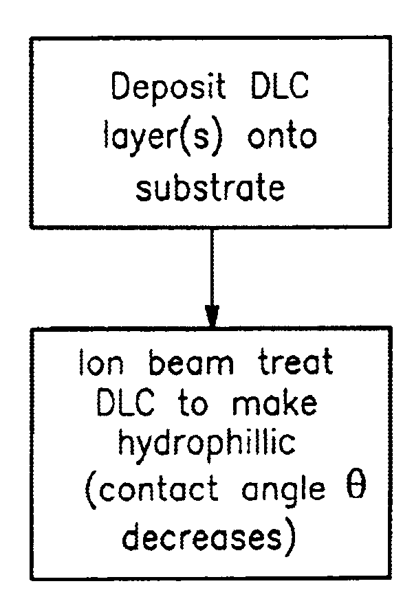
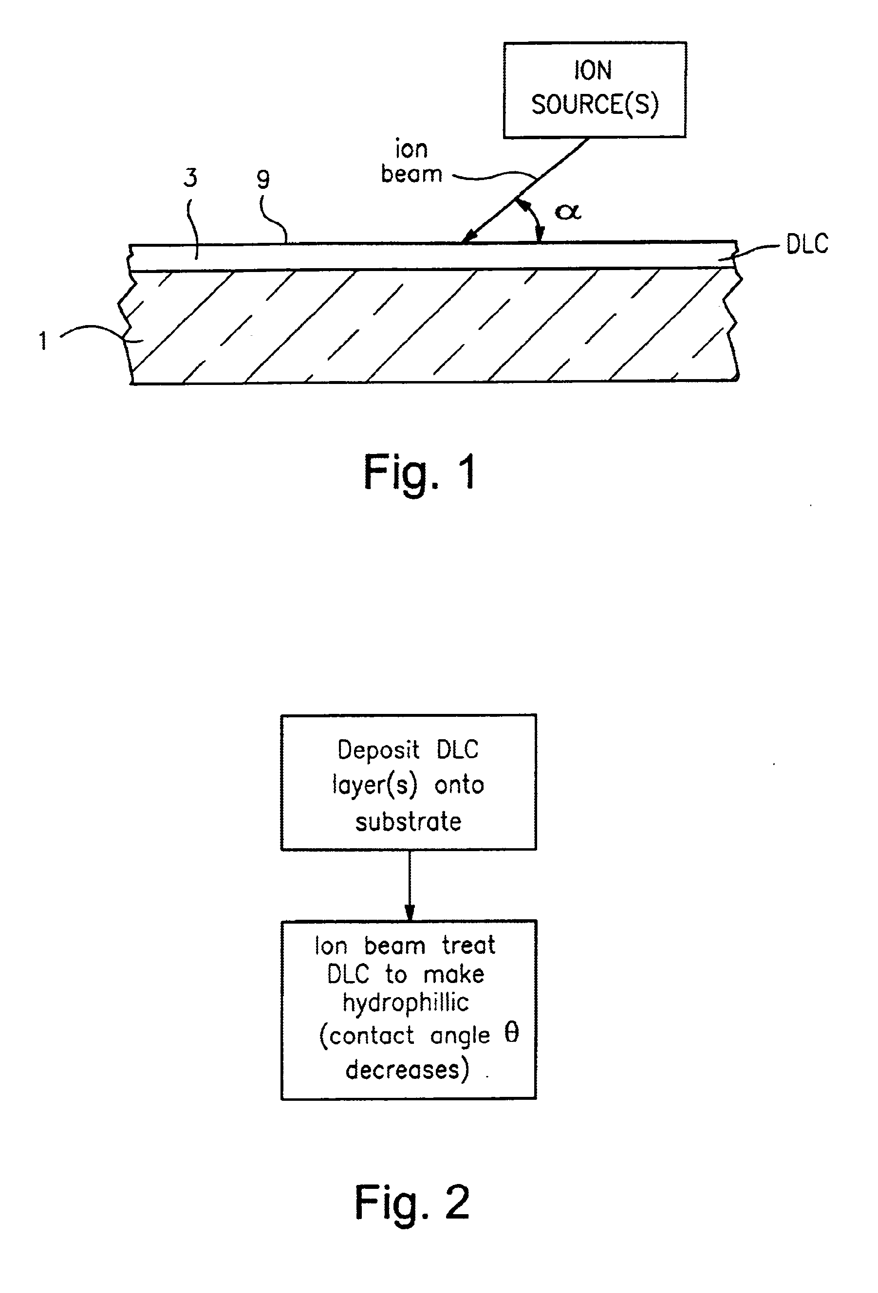
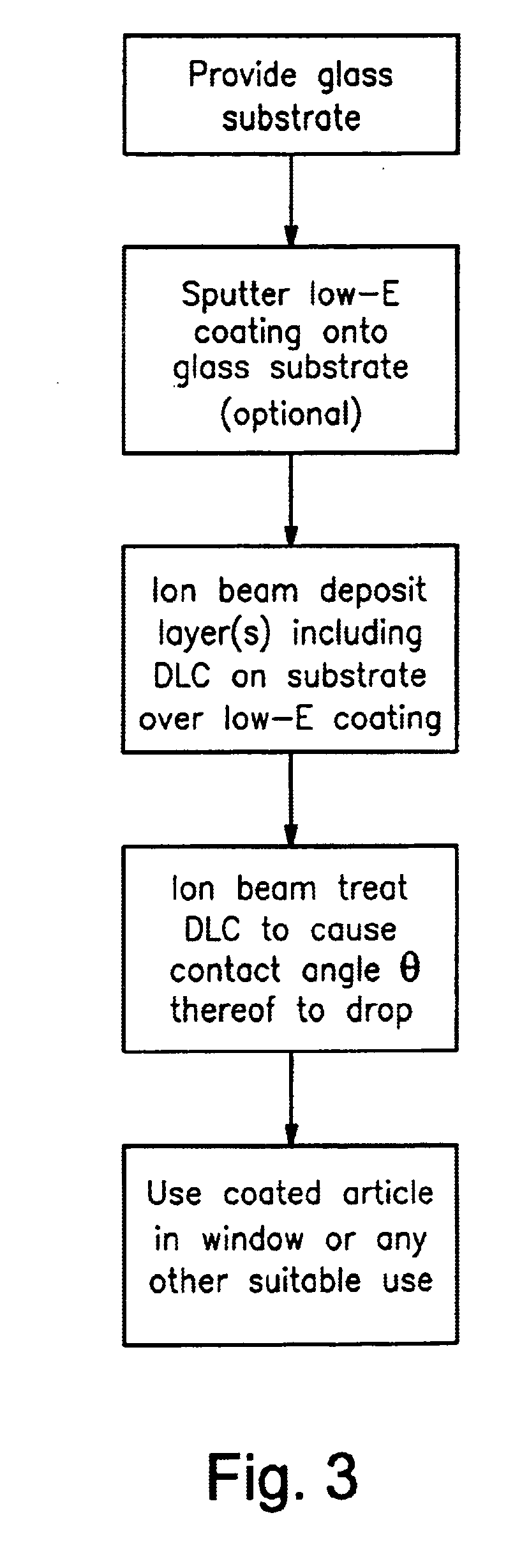
Another object of certain embodiments of this invention is to ion beam treat a layer comprising DLC in order to cause its contact angle θ to drop / decrease. In certain embodiments, it has been found that ion beam treating a DLC inclusive layer (e.g., using oxygen and nitrogen gases, and / or water vapor gas, for example, in the ion source) oxidizes the surface of the DLC inclusive layer thereby causing its contact angle θ to quickly drop in a short period of time. In certain example embodiments, the ion beam treatment causes the contact angle θ of the DLC inclusive layer to drop at least about 20%, more preferably at least about 40%, even more preferably at least about 50%, and most preferably at least about 60%. The contact angle θ of the DLC inclusive layer before ion beam treatment may or may not be hydrophilic, but after said ion beam treatment in certain example embodiments the contact angle θ is less than about 25 degrees, more preferably less than about 20 degrees, even more preferably less than about 15 degrees, and most preferably less than about 10 degrees, and sometimes as low a 5 degrees or less.

Problems solved by technology

Unfortunately, certain hydrophilic coatings are not as durable and / or hard as would otherwise be desired and thus are not efficient from a practical point of view for applications such as automotive windshields and / or other types of windows or mirrors.
While this process of making a hydrophilic DLC inclusive layer works well, it takes much time.

Method used


Image

  • Method of ion beam treatment of DLC in order to reduce contact angle
  • Method of ion beam treatment of DLC in order to reduce contact angle
  • Method of ion beam treatment of DLC in order to reduce contact angle

Examples


example

The following hypothetical Example is for purposes of example only, and is not limiting. On a 2 mm thick clear glass substrate, a DLC layer 3 was ion beam deposited to a thickness of 14.69 angstroms (Å) using acetylene (C2H2) feedstock gas (145 sccm) at a linear velocity of 100 inches / minute, at 2970 V and 0.57 amps. The layer 3 was not doped with any of the dopants B, N, etc. The result was a DLC layer 3 of a-taC:H, having an initial contact angle θ of 73.47 degrees. Then, the coated article was then ion beam treated using a gas including a mixture of oxygen and nitrogen in the ion source. The ion beam for the treatment hit the surface 9 of layer 3 at an angle α of about 45 degrees. An energy of from 100-3,000 eV (e.g., 1,500 eV) was used. Following the ion beam treatment of surface 9, the coated article including substrate 1 with DLC layer 3 thereon had a contact angle θ which had dropped all the way down to 9 degrees. Thus, it can be seen that the contact angle decreased by about...


PUM

PropertyMeasurementUnit
Fractionaaaaaaaaaa
Fractionaaaaaaaaaa
Fractionaaaaaaaaaa

Abstract

A method is provided for ion treating diamond-like carbon (DLC) in order to reduce contact angle thereof. For example, a substrate is coated with a layer(s) or coating(s) that includes, for example, amorphous carbon in a form of DLC. The DLC is then ion beam treated in a manner so as to cause the contact angle θ thereof to decrease. In certain example embodiments, at least oxygen gas is used in an ion beam source(s) that generates the ion beam(s) used for the ion beam treatment.

Description

Certain example embodiments of this invention relate to a hydrophilic coating including diamond-like carbon (DLC) provided on (directly or indirectly) a substrate of glass, plastic, or the like, and a method of making the same. More particularly, this invention relates to a DLC inclusive coating that is ion beam treated after its deposition in order to cause the coating to either become hydrophilic and / or to simply reduce its contact angle θ.BACKGROUND OF THE INVENTIONIt is often desirable to provide a hydrophilic coating (e.g., anti-fog coating) on a substrate such as an automotive windshield, automotive window, automotive mirror, architectural mirror, bathroom mirror, architectural window, or the like. Such coatings may reduce the likelihood of water drops deposited on the substrate taking globular shape(s), thereby enabling visibility to be improved. In other words, hydrophilic coatings function to reduce bead-like condensation on substrate surfaces (e.g., on the interior surface...

Claims


Application Information

Patent Timeline
IPC IPC(8): C03C17/36C03C17/34C03C17/22
CPCC03C17/22C03C17/3441C03C17/36C03C17/3618C03C17/3626C03C17/3634C03C17/366C03C17/3644Y10T428/30C03C2217/282C03C2217/75C03C2217/78C03C2218/32
Inventor VEERASAMY, VIJAYEN S.THOMSEN, SCOTT V.
Owner GUARDIAN GLASS LLC
Learn More