Thermal fuse

a technology of thermal fuse and flux coating, which is applied in the manufacture of emergency protective devices, electrical equipment, basic electric elements, etc., can solve the problem that the image processing method using ccd cameras and the like cannot inspect the flux coating quantity of thermal fuse with high accuracy, and achieve the effect of accurate inspection

Inactive Publication Date: 2005-01-04
PANASONIC CORP
View PDF20 Cites 24 Cited by
  • Summary
  • Abstract
  • Description
  • Claims
  • Application Information

AI Technical Summary

Benefits of technology

At least either of the first insulation film or the second insulation film of this thermal fuse is transparent or translucent, and the flux has the color scale from 4 to 16. So the image processing method can inspect thermal fuse on flux coating without inspection error of judging as “transparent” owing to too small color scale of flux, and can easily distinguish between flux and fusible alloy due to not too large color scale of flux. Consequently, the thermal fuse is disclosed whose flux coating quantity on fusible alloy can be accurately inspected by the image processing method.

Problems solved by technology

Thermal fuse coated with insufficient quantity of flux, therefore, must be rejected in production inspection process as thermal fuse with insufficient flux shows poor characteristics in cutting-off action.
As mentioned above, the drawback in conventional art is that image processing method using CCD camera and the like can not inspect flux coating quantity of thermal fuse with high accuracy due to fluctuation in color of flux 3.

Method used


Image

  • Thermal fuse
  • Thermal fuse
  • Thermal fuse

Examples


exemplary embodiment 1

(Exemplary Embodiment 1)

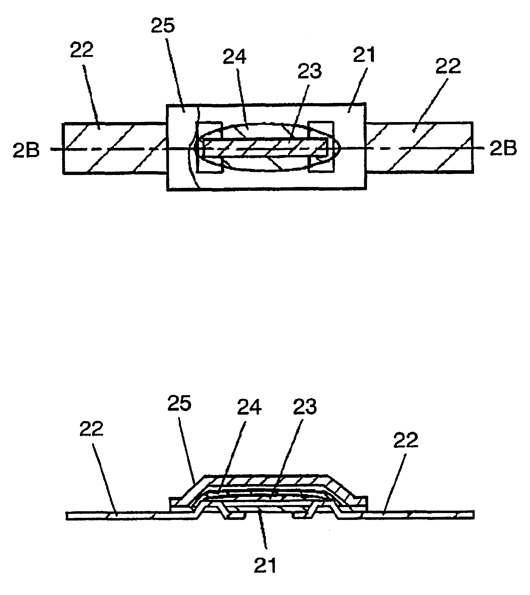
FIG. 1A is a plan view, partly in section, showing a thermal fuse used in exemplary embodiment 1. FIG. 1B is a sectional view taken along the line 1B—1B in FIG. 1A.

A thermal fuse used in exemplary embodiment 1 comprises a sheet shaped first insulation film 11, composed of resin such as polyethylene terephthalate, polyethylene naphthalete or the like, coupled with a pair of metal terminals 12 having narrower width than first insulation film 11 as shown in FIGS. 1A and 1B. A pair of metal terminals 12, stripe shaped or line shaped, is composed of highly electrical conductive metal such as copper, nickel or the like whose surface is plated by solder, tin, copper or the like. Being placed above first insulation film 11, fusible alloy 13 is coupled between ends of metal terminals 12. Fusible alloy 13 consists of one of following metals: tin, lead, zinc, bismuth, indium, cadmium, silver and copper, or an alloy composed of a plurality of above mentioned metals.

Fusib...

exemplary embodiment 2

(Exemplary Embodiment 2)

The thermal fuse disclosed in exemplary embodiment 2 has a height of an internal space formed between first insulation film 11 and second insulation film 15 described in exemplary embodiment 1:not lower than 0.20 mm but lower than 0.35 mm and a color scale of flux 14 coated on fusible alloy 13:from 6 to 16.

As configured above, flux 14 has a limited range of color scale of from 6 to 16, narrower than first exemplary embodiment, corresponding to the lower height of an internal space formed between first insulation film 11 and second insulation film 15. Consequently, the image processing method can inspect thermal fuse on flux coating without any error due to judging as “transparent”, and can easily distinguish between flux 14 and fusible alloy 13, resulting a more accurate inspection on coating quantity of flux 14.

exemplary embodiment 3

(Exemplary Embodiment 3)

The thermal fuse disclosed in exemplary embodiment 3 has a height of an internal space formed between first insulation film 11 and second insulation film 15 described in exemplary embodiment 1:not lower than 0.35 mm but lower than 0.65 mm and a color scale of flux 14 coated on fusible alloy 13:from 5 to 15.

As configured above, flux 14 has a limited range of color scale, neither too large nor too small, corresponding to height of an internal space formed between first insulation film 11 and second insulation film 15.

Consequently, the image processing method can inspect thermal fuse on flux coating without any error due to judging as “transparent”, and can easily distinguish between flux 14 and fusible alloy 13, resulting a more accurate inspection on coating quantity of flux 14.


PUM

PropertyMeasurementUnit
heightaaaaaaaaaa
heightaaaaaaaaaa
heightaaaaaaaaaa

Abstract

Quantity of flux coated on fusible alloy of a thermal fuse disclosed can be inspected accurately by an image processing method. The thermal fuse comprises:
    • (a) first insulation film 11 coupled with a pair of metal terminals 12;
    • (b) fusible alloy 13 coupled between ends of the metal terminals 12, being placed above first insulation film 11;
    • (c) flux 14 coated on fusible alloy 13; and
    • (d) second insulation film 15 disposed on first insulation film 11 so that an internal space is formed, being placed above fusible alloy 13,
    • wherein at least either of first insulation film 11 or second insulation film 15 is transparent or translucent, and flux 14 has the Gardner color scale from 4 to 16.

Description

TECHNICAL FIELDThe present invention relates to a thermal fuse.BACKGROUND ARTRecent development of thin downsized secondary battery requires strongly a low-profile thermal fuse. Because current portable devices such as cellphones, notebook computers or video cameras and the like mainly adopt high capacity lithium-ion or lithium-polymer secondary batteries used in conjunction with thermal fuses.A typical thermal fuse is composed of fusible alloys having low melting temperature.A known conventional thermal fuse is disclosed in the Japanese Patent Application Non-Examined Publication No. H2-291624.FIG. 3A illustrates a plan view, partly in section, showing a conventional thermal fuse. FIG. 3B illustrates a sectional view taken along the line 3B—3B in FIG. 3A.As shown in FIGS. 3A and 3B, a conventional thermal fuse has a pair of metal terminal 1 each mounted on bottom surface of insulation film 2, protruding a portion of metal terminals 1 from bottom surface to out of upper surface of i...

Claims


Application Information

Patent Timeline
Patent Type & Authority Patents(United States)
IPC IPC(8): H01H37/00H01H37/76
CPCH01H37/761Y10T29/49107H01H2037/768
Inventor SENDA, KENJIMUKAI, TAKAHIRO
Owner PANASONIC CORP
Why Eureka
Try Eureka