Method and apparatus for monitoring optical signal performance in wavelength division multiplexing system

a wavelength division multiplexing and optical signal technology, applied in the direction of optical radiation measurement, instruments, photoelectric discharge tubes, etc., can solve the problems of not entirely new, equipment cannot be used for wdm system without fiber amplifiers, and it is difficult to achieve a more efficient optical space array. , to achieve the effect of improving the resolution of wavelength division multiplexed optical signals

Inactive Publication Date: 2005-01-04
SAMSUNG ELECTRONICS CO LTD
View PDF7 Cites 35 Cited by
  • Summary
  • Abstract
  • Description
  • Claims
  • Application Information

AI Technical Summary

Benefits of technology

A preferably used fiber bragg grating is a tilted fiber bragg grating that generates an amplified spontaneous emission signal having a reference wavelength of a main mode and a side mode, respectively, by either reflecting or absorbing the main mode reference wavelength and the side mode reference wavelength according to an inclination angle. Fortunately, when the tilted fiber bragg grating is employed, the reference wavelength of the amplified spontaneous emission is increased by m

Problems solved by technology

However, when optical equipment like the diffraction grating and the photo diode array are employed, it is difficult to achieve a more efficient optical space array.
In fact, this problem is not entirely new to anyone skilled in the art who is well aware of the difficulty with the precise measurement of the optical wavelength, the optical power, and the optical signal to noise ratio especially when the optical space array has not been done accurately.
Despite such a configuration, the equipment could not be

Method used


Image

  • Method and apparatus for monitoring optical signal performance in wavelength division multiplexing system
  • Method and apparatus for monitoring optical signal performance in wavelength division multiplexing system
  • Method and apparatus for monitoring optical signal performance in wavelength division multiplexing system

Examples


Embodiment Construction

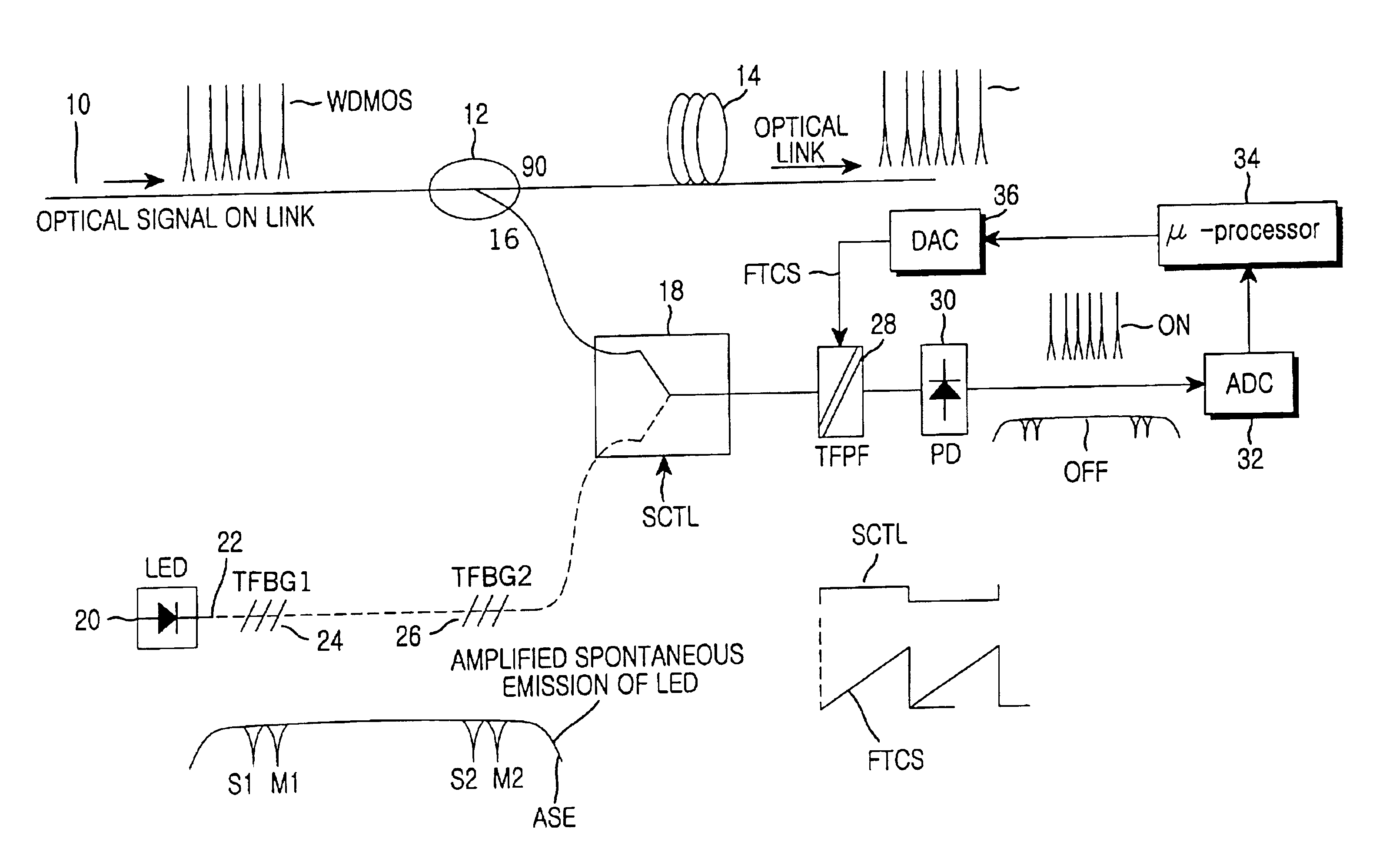
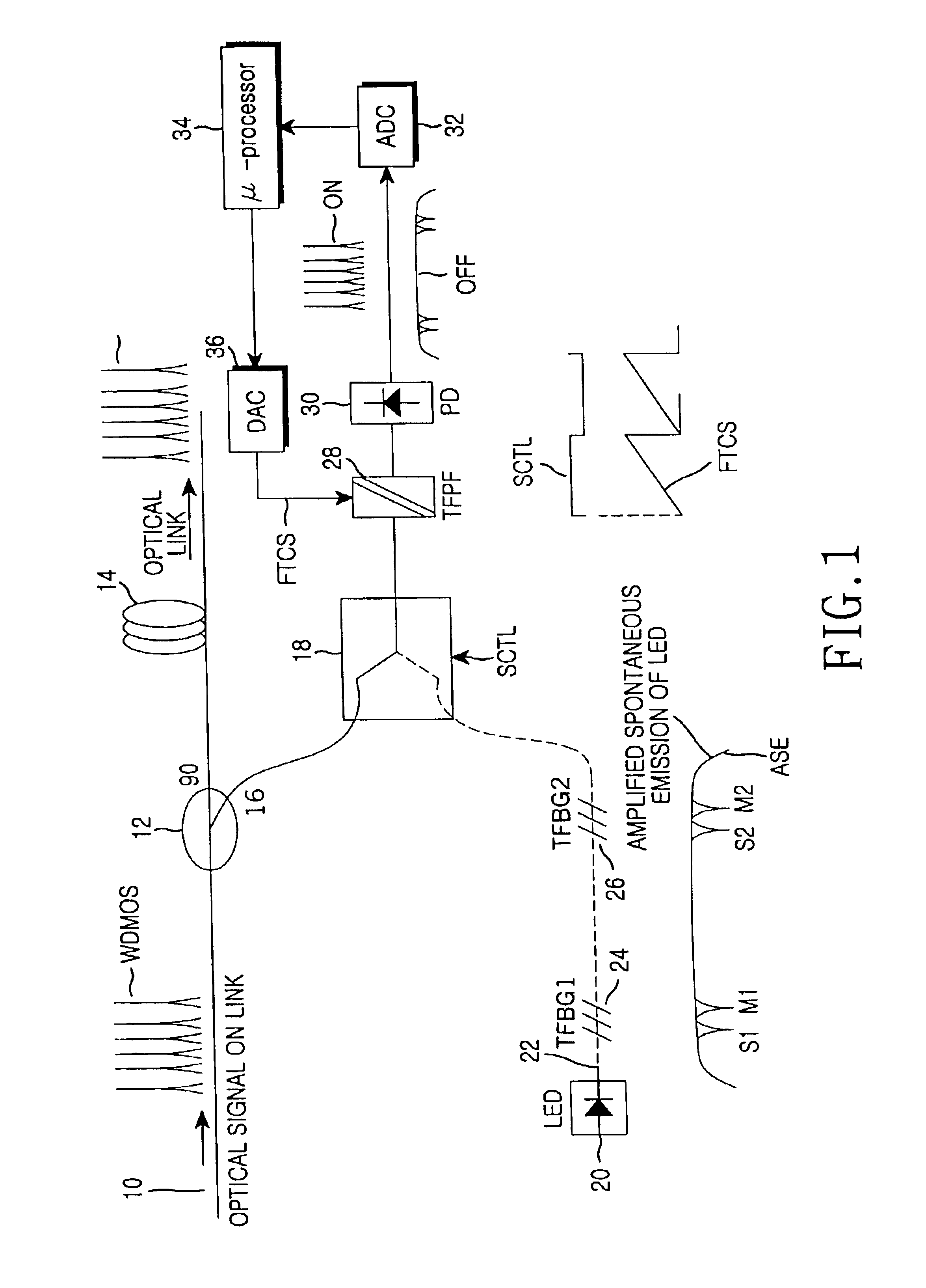
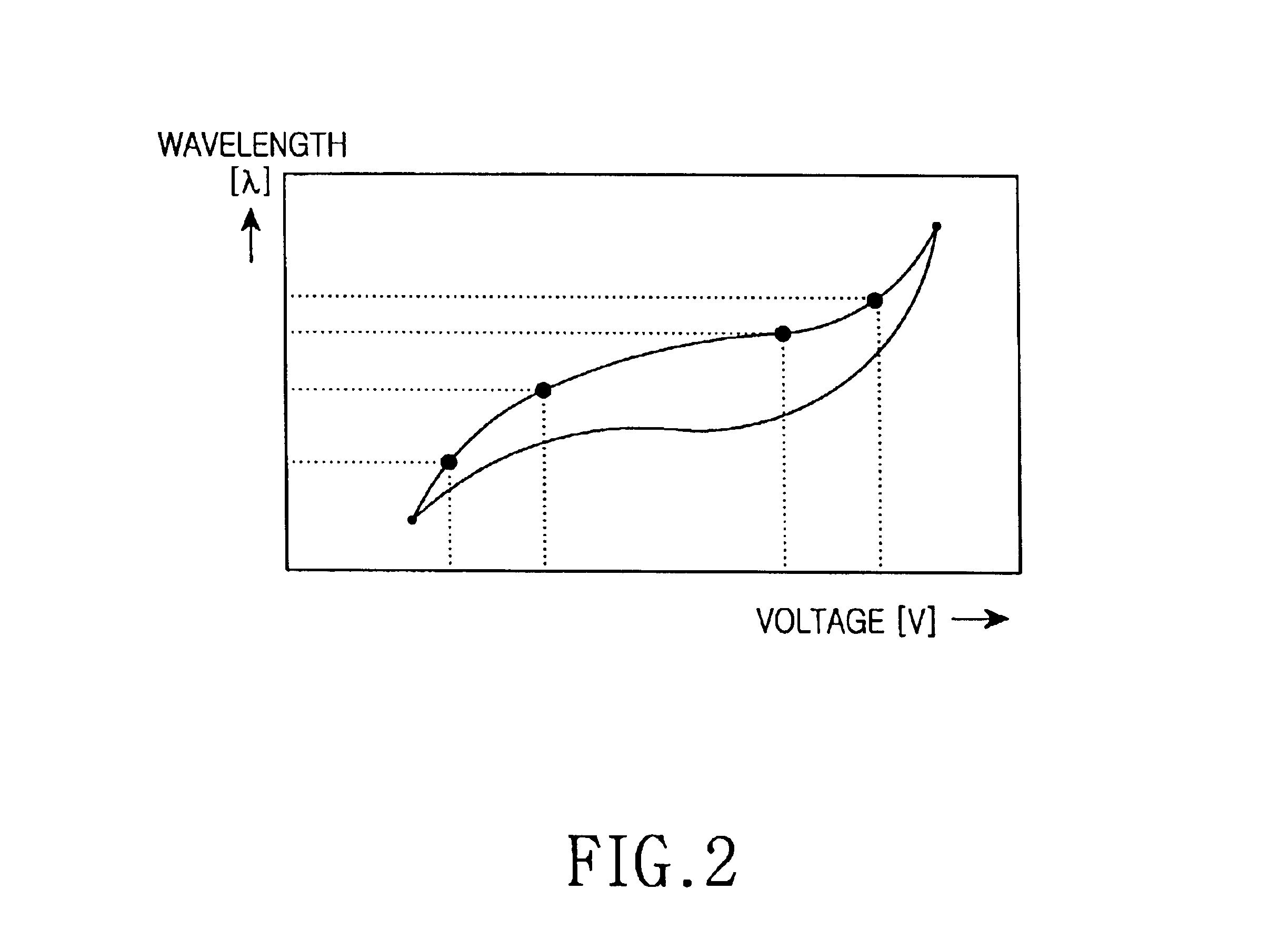
While the present invention will be described more fully hereinafter with reference to the accompanying drawings, in which preferred embodiments of the present invention are shown, it is to be understood at the outset of the description which follows that persons of skill in the appropriate arts may modify the invention here described while still achieving the favorable results of this invention. Accordingly, the description which follows is to be understood as being a broad, teaching disclosure directed to persons of skill in the appropriate arts, and not as limiting upon the present invention.

Illustrative embodiments of the invention are described below. In the interest of clarity, not all features of an actual implementation are described. In the following description, well-known functions or constructions are not described in detail since they would obscure the invention with unnecessary detail. It will be appreciated that, in the development of any actual embodiment, numerous i...


PUM


Abstract

An apparatus for monitoring a wavelength division multiplexed optical signal transmitted onto a main optical path includes: an amplified spontaneous light emitter for generating an amplified spontaneous emission signal and transmitting the same to onto a reference optical path; at least one fiber bragg grating for sending out an amplified spontaneous emission signal having a reference wavelength by reflecting or absorbing only that part of the amplified spontaneous emission signal which consists of a reflection wavelength or an absorbance wavelength; an optical switch for outputting at least one of the wavelength division multiplexed optical signals branched from the main optical path or one of the amplified spontaneous emissions including the reference wavelengths in response to a switching control signal input; a tunable optical filter for filtering the optical signal outputted from the optical switch using varied filter characteristics, and for outputting the filtered optical signal; and a control unit for measuring an optical wavelength, an optical power and an optical signal to noise ratio of the wavelength division multiplexed optical signal based on the analyzed reference wavelength.

Description

CLAIM OF PRIORITYThis application makes reference to, incorporates the same herein, and claims all benefits accruing under 35 U.S.C. §119 from my application entitled APPARATUS FOR OPTICAL SIGNAL PERFORMANCE MONITORING IN WAVELENGTH DIVISION MULTIPLEXING SYSTEM filed with the Korean Industrial Property Office on Sep. 22, 2001 and there duly assigned Serial No. 58863 / 2001.BACKGROUND OF THE INVENTION1. Technical FieldThe present invention relates generally to an apparatus for monitoring optical signal performance in a wavelength division multiplexing system, and in particular, to an apparatus for monitoring optical signal performance in a link section without a fiber amplifier.2. Related ArtA wavelength division multiplexing (WDM) optical communication system measures wavelength, optical power, and optical signal to noise ratio (OSNR) of an optical signal being transmitted through an optical transmission line on an optical link in order to monitor the performance of the optical signal...

Claims


Application Information

Patent Timeline
IPC IPC(8): H04B10/08H04B10/077H04B10/079
CPCH04B10/07955H04B10/077H04B10/07H04B10/2581
Inventor KWON, SEO-WON
Owner SAMSUNG ELECTRONICS CO LTD
Why Eureka
Try Eureka