Method and apparatus for compensation of time-varying optical properties of gas in interferometry

a technology of optical properties and compensation methods, applied in the field of displacement measurement of interferometers, can solve the problems of inability to decouple the change in propagation direction, the refractive index of gas can vary, and the situation becomes more complicated

Inactive Publication Date: 2005-01-04
ZYGO CORPORATION
View PDF9 Cites 51 Cited by
  • Summary
  • Abstract
  • Description
  • Claims
  • Application Information

AI Technical Summary

Benefits of technology

They can provide accurate interferometry measurements in the presence of time-varying optical properties of gas in the measurement and/or reference beam(s) using single wavelength interferometry techniques (i.e., non-dispersive interferometry techniques). They can compensate for optical effe

Problems solved by technology

As discussed above, time-varying optical properties of gas in an interferometer beam path give rise to uncertainty in interferometry measurements because, even if all the components are stationary, the refractive index of the gas can vary.
The situation becomes more complicated when components of the interferometer are not stati

Method used


Image

  • Method and apparatus for compensation of time-varying optical properties of gas in interferometry
  • Method and apparatus for compensation of time-varying optical properties of gas in interferometry
  • Method and apparatus for compensation of time-varying optical properties of gas in interferometry

Examples


first embodiment

Referring now to FIG. 3, an embodiment of an angle interferometer is shown schematically and makes angle measurements in one plane of the average direction of propagation of beam 712 relative to a predefined optical axis. The first embodiment comprises beam-shearing assembly generally shown at element numeral 830, analyzer 840, lens 846, detector 860, and electronic processor 870. For heterodyne interferometry, input beam 712 comprises two orthogonally polarized optical beam components having a difference in frequencies of f1. The planes of polarization of the two orthogonally polarized components are parallel and orthogonal to the plane of FIG. 3, respectively.

Beam-shearing assembly 830 introduces a lateral shear Sa1 between the two orthogonally polarized beams 850 and 852, respectively (see FIG. 3). A portion of each of the spatially sheared output beams 850 and 852 are transmitted by analyzer 840 as components 854 and 856, respectively. Analyzer 840 is orientated so that beam com...

second embodiment

beam-shearing assembly 830 is shown diagrammatically in FIG. 7 and comprises two prisms 8330 and 8332 and polarization beam-splitter interface 8340. A first component of input beam 712 is transmitted twice by polarization beam-splitter interface 8340 and reflected by facets of prisms 8330 and 8332 to form output beam 8350. A second component of input beam 712 is reflected twice by polarization beam-splitter interface 8340 and reflected by facets of prisms 8330 and 8332 to form output beam 8352.

The two prisms 8330 and 8332 and polarization beam-splitter interface 8340 exhibit properties the same as a Penta prism with respect to relationship of the direction of propagation of beam 712 and the directions of propagation for beams 8350 and 8352. Prisms 8330 and 8332 are preferably isomorphic with relative sizes selected to introduce a beam shear Sa3 between beams 8350 and 8352. The optical paths in refractive media are substantially the same for beam 8350 and 8352. The remaining descript...


PUM


Abstract

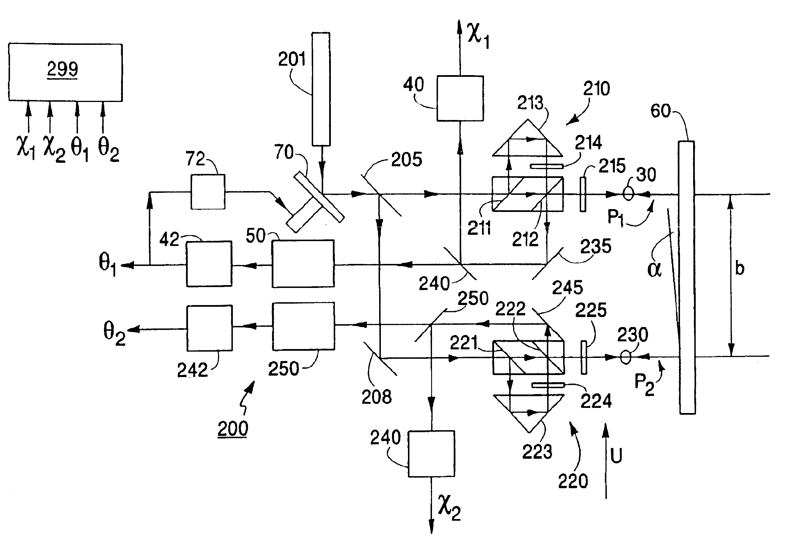
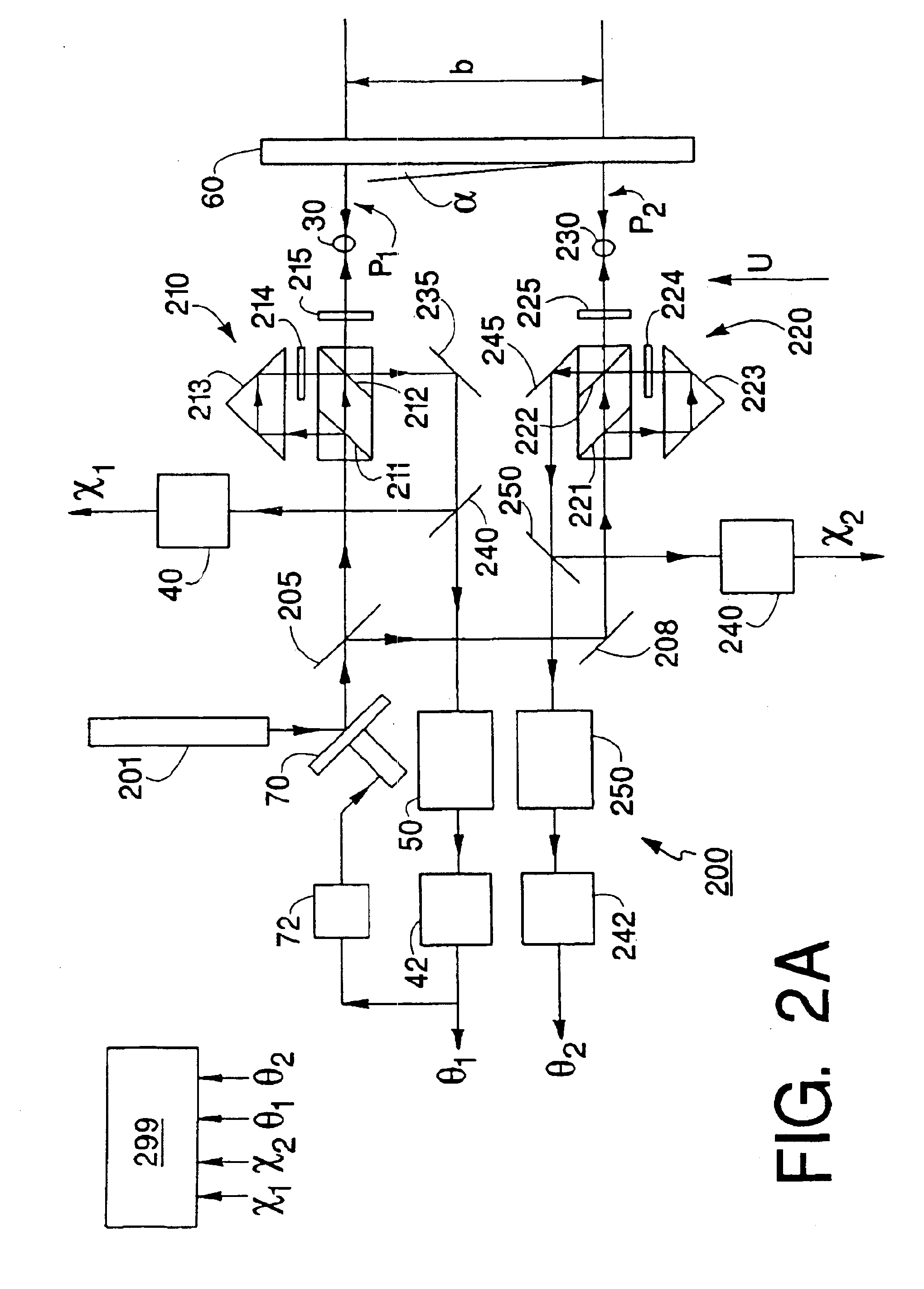
In general, in one aspect, the invention features a method, including interferometrically measuring first and second optical path lengths to a measurement object along respective first and second paths, wherein the measurement of the optical path lengths includes directing first and second measurement beams to reflect from the measurement object, measuring propagation directions of the first and second measurement beams, compensating the first measured optical path length for time-varying optical properties of gas in the first path based on the first and second measured optical path lengths and the first and second measured propagation directions.

Description

BACKGROUNDDisplacement-measuring interferometers monitor changes in the position of a measurement object relative to a reference object based on an optical interference signal. The interferometer generates the optical interference signal by overlapping and interfering a measurement beam reflected from the measurement object with a reference beam reflected from the reference object.In many applications, the measurement and reference beams have orthogonal polarizations and different frequencies. The different frequencies can be produced, for example, by laser Zeeman splitting, by acousto-optical modulation, or internal to the laser using birefringent elements or the like. The orthogonal polarizations allow a polarizing beam splitter to direct the measurement and reference beams to the measurement and reference objects, respectively, and combine the reflected measurement and reference beams to form overlapping exit measurement and reference beams. The overlapping exit beams form an out...

Claims


Application Information

Patent Timeline
IPC IPC(8): G01B9/02G01B11/00G03F7/20H01L21/027
CPCG01B9/02019G01B9/02003G01B9/0207G01B9/02098G01B9/02027G01B2290/45G01B2290/70
Inventor HILL, HENRY A.
Owner ZYGO CORPORATION
Why Eureka
Try Eureka