PFC-PWM controller having a power saving means

a controller and power saving technology, applied in the direction of electric variable regulation, process and machine control, instruments, etc., can solve the problems of serious power loss, reduce the power factor, and the traditional switching-mode power supply has some drawbacks, so as to reduce the number of pins, reduce the power factor, and reduce the cost

Inactive Publication Date: 2005-01-04
SEMICON COMPONENTS IND LLC
View PDF5 Cites 252 Cited by
  • Summary
  • Abstract
  • Description
  • Claims
  • Application Information

AI Technical Summary

Benefits of technology

Another objective of the present invention is to synchronize the PWM signal and the PFC signal in an interleaved manner so that a smoother energy delivery from the PFC circuit to the PWM circuit can be effectively achieved and as well increasing power transmission efficiency. The PFC-PWM controller according to the present invention uses a pulse signal to accomplish this objective.
Another objective of the present invention is to provide a pulse-width limiter to establish a maximum on-time for the PWM signal so that switching components such as the transformer and the transistor can be effectively prevented from being saturated.
Still another objective of the present invention is to eliminate the pin-count of the PFC-PWM controller.
According to one aspect of the present invention, the PFC-PWM controller includes a current synthesizer that generates a bias current in response to a PFC-feedback voltage and a PWM-feedback voltage. The bias current will modulate an oscillator frequency to vary the switching frequency of the PFC signal and the PWM signal. When the power converter operates under light-load conditions, the bias current will be reduced to increase the switching period. This feature can dramatically reduce the power consumption of the PFC-PWM controller.

Problems solved by technology

However, traditional switching-mode power supplies have some drawbacks.
This is undesirable for a switching-mode power supply, because it reduces the power factor.
For applications that consume 70 watts or more, this could be a serious source of power loss.
Another drawback of switching mode power converters is that line harmonics are produced whenever the line current is not sinusoidal.
The harmonic currents do not contribute to the load power, but they do cause excess heat generation in the power contribution system.
One drawback of traditional power factor correction schemes is that they do not reduce power consumption sufficiently to comply with recent environmental regulations.
However, traditional switching-mode power supplies with power factor correction still operate at a specific PWM switching frequency during standby.
Since the power consumption of a switching-mode power converter is directly proportional to the switching frequency of the PWM signal and the PFC signal, prior-art switching-mode power supplies fail to minimize power consumption during standby.

Method used


Image

  • PFC-PWM controller having a power saving means
  • PFC-PWM controller having a power saving means
  • PFC-PWM controller having a power saving means

Examples


Embodiment Construction

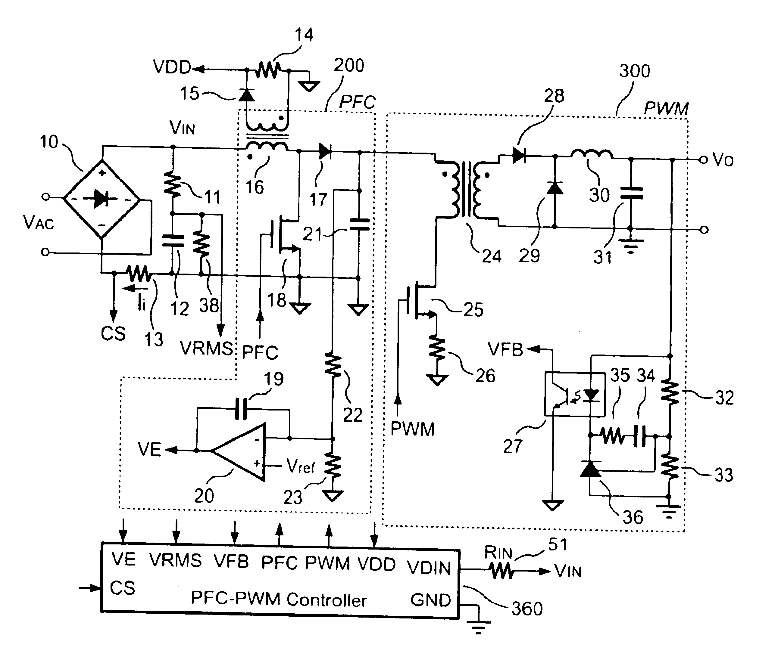
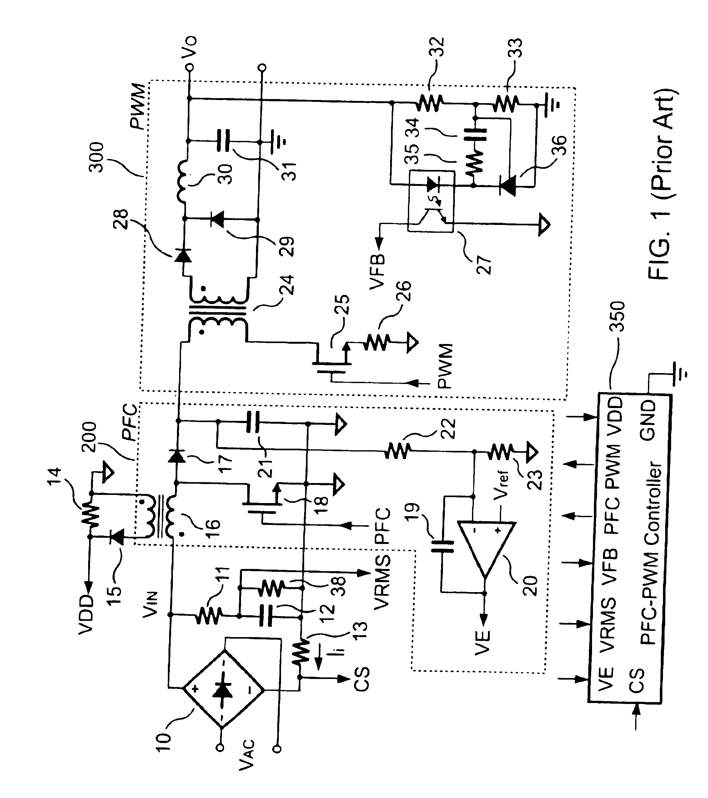
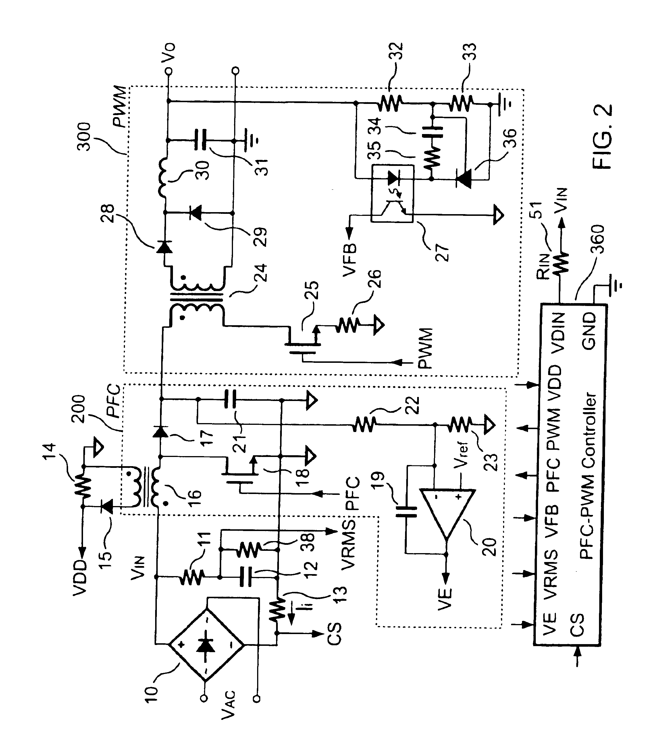
FIG. 1 shows a conventional forward power converter equipped with a PFC-PWM controller 350 to drive a PFC circuit 200 and a PWM circuit 300. A resistor 22 and a resistor 23 form a resistor divider to sense the output voltage of the PFC circuit 200 from a cathode of a rectifying diode 17. An operational amplifier 20 generates a PFC-feedback voltage VE that is varied in inverse proportion to the voltage at the junction of the resistors 22 and 23. The PWM circuit 300 can be viewed as the load of the PFC circuit 200. An increased load will cause the output voltage of the PWM circuit 300 to decrease, and with that the output voltages of the PFC circuit 200 and the PWM circuit 300 will also decrease accordingly. On the other hand, when the load decreases, the output voltages of the PFC circuit 200 and PWM circuit 300 will also increase. To obtain a sinusoidal line current waveform, the PFC-PWM controller 350 accepts several input signals. The input signals include the line current informa...


PUM


Abstract

A PFC-PWM controller with a power saving means is disclosed. A built-in current synthesizer generates a bias current in response to feedback voltages sampled from the PWM circuit and the PFC circuit. The bias current modulates the oscillation frequency to further reduce the switching frequencies of the PWM signal and the PFC signal under light-load and zero-load conditions. Thus, power consumption is greatly reduced. The PFC and the PWM switching signals interleave each other, so that power can be transferred more smoothly from the PFC circuit to the PWM circuit. The saturation of the switching components can be avoided by limiting the maximum on-time of the PWM signal. Further, an external resistor is used to start up the PFC-PWM controller and provide an AC template signal for PFC control.

Description

BACKGROUND OF THE INVENTION1. Field of the InventionThe present invention generally relates to a forward switching mode power converter. More particularly, the present invention relates to a PFC-PWM controller having a power saving means. The present invention teaches a forward power converter with power factor correction in the front end.2. Description of the Related ArtSwitching-mode power converters have been widely used in many electronic appliances over the last few decades. Switching-mode power converters have several advantages over linear power converters, including higher power conversion efficiency, lighter weight, and smaller size.However, traditional switching-mode power supplies have some drawbacks. A typical switching mode power converter conducts a non-sinusoidal line current in short pulses that are in phase with the line voltage. This is undesirable for a switching-mode power supply, because it reduces the power factor. Ideally, a switching mode power converter shou...

Claims


Application Information

Patent Timeline
Patent Type & Authority Patents(United States)
IPC IPC(8): H02M1/00H02M1/42
CPCH02M1/4225H02M2001/0032Y02B70/16Y02B70/126H02M2001/007Y02B70/10H02M1/0032H02M1/007
Inventor YANG, TA-YUNGLIN, JENN-YU G.CHEN, CHERN-LIN
Owner SEMICON COMPONENTS IND LLC
Why Eureka
Try Eureka